En-4
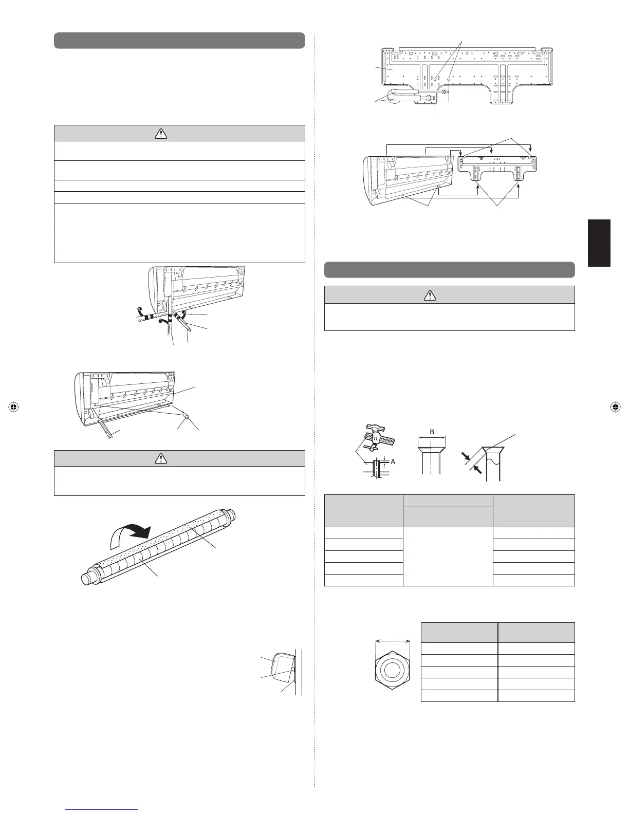
6.5. Forming the drain hose and pipe
[Rear piping, Right piping, Bottom piping]
• Install the indoor unit piping in the direction of the wall hole and bind the drain hose and
pipe together with vinyl tape.
• Install the piping so that the drain hose is at the bottom.
• Wrap the pipes of the indoor unit that are visible from the outside with decorative tape.
[For Left rear piping, Left piping]
Interchange the drain cap and the drain hose.
CAUTION
Insert drain hose and drain cap securely. Drain should slope down to avoid water
leakage.
When inserting, be sure not to attach any material besides water. If any other
material is attached, it will cause deterioration and water leakage.
After removing drain hose, be sure not to forget mounting drain cap.
Be sure to fi x the drain hose with tape to the bottom of piping.
Prevent drain water freezing under low temperature environment.
When installing indoor unit’s drain hose outdoors, necessary measure for frost protec-
tion should be taken to prevent drain water freezing.
Under low temperature environment (when outdoor temperature under 0 °C), after cool-
ing operation is executed, water in the drain hose could be frozen. Once drain water is
frozen, the drain hose will be blocked and water leakage may result at the indoor unit.
Right piping
Bind with vinyl tape
Indoor unit drain hose
(bottom)
Pipe (top)
Rear piping
Bottom piping
Drain cap
Indoor unit
drain hose
Remove the drain cap by pull-
ing at the projection at the end
of the cap with pliers, etc.
For left outlet piping, cut
off the piping outlet cutting
groove with a hacksaw.
CAUTION
Insert the drain hose and drain cap into the drain port, making sure that it comes
in contact with the back of the drain port, and then mount it. If the drain hose is
not connected properly, leaking will occur.
• Attach the Drain hose insulation to the drain hose.
Drain hose insulation
Drain hose
• For left piping and left rear piping, align the marks on the wall hook bracket and shape
the connection pipe.
• Bend the connection piping at the bend radius of 100 mm or more and install no more
than 35 mm from the wall.
• After passing the indoor piping and drain hose through the wall hole, hang the indoor unit
on the hooks at the top and bottom of the wall hook bracket.
[Installing the indoor unit]
• Hang the indoor unit from the hooks at the top
of the wall hook bracket.
• Insert the spacer, etc. between the indoor unit and
the wall hook bracket and separate the bottom of
the indoor unit from the wall.
Indoor unit
Wall hook bracket
(Spacer)
Wall hook
bracket
Alignment marks
Small piping
Connection
piping
Large piping
Top hooks
Indoor
unit
(Fitting)
Bottom hooks
Wall hook
bracket
After hooking the indoor unit to the top hook, hook the fi ttings of the indoor unit to the 2
bottom hooks while lowering the unit and pushing it against the wall.
6.6.
Flare connection (Pipe connection)
WARNING
Tighten the fl are nuts with a torque wrench using the specifi ed tightening method.
Otherwise, the fl are nuts could break after a prolonged period, causing refrigerant to
leak and generate hazardous gas if the refrigerant comes into contact with a fl ame.
6.6.1. Flaring
Use special pipe cutter and fl are tool exclusive for R410A.
(1)
Cut the connection pipe to the necessary length with a pipe cutter.
(2) Hold the pipe downward so that cuttings will not enter the pipe and remove any burrs.
(3) Insert the fl are nut (always use the fl are nut attached to the indoor unit(s) and outdoor
unit or branch box respectively) onto the pipe and perform the fl are processing with a
fl are tool. Use the special R410A fl are tool, or the conventional fl are tool. Leakage of re-
frigerant may result if other fl are nuts are used.
(4) Protect the pipes by pinching them or with tape to prevent dust, dirt, or water from enter-
ing the pipes.
L
Check if [L] is flared uniformly and
is not cracked or scratched.
Pipe
Die
Pipe outside diameter
[mm (in.)]
Dimension A [mm]
Dimension B
-
0
0.4
[mm]
Flare tool for R410A,
clutch type
6.35 (1/4)
0 to 0.5
9.1
9.52 (3/8) 13.2
12.70 (1/2) 16.6
15.88 (5/8) 19.7
19.05 (3/4) 24.0
When using conventional fl are tools to fl are R410A pipes, the dimension A should be approxi-
mately 0.5 mm more than indicated in the table (for fl aring with R410A fl are tools) to achieve
the specifi ed fl aring. Use a thickness gauge to measure the dimension A.
Width across flats
 Loading...