Do you have a question about the Fujitsu AUG12LVLB and is the answer not in the manual?
Explains the cooling cycle and capacity control.
Lists error codes displayed on unit and remote controller.
How compressor frequency is managed based on temperature.
How compressor frequency is managed in heating.
Control logic for the indoor unit during dry operation.
Table detailing fan speeds for various modes and models.
How fan operation works when only fan mode is selected.
Fan control during automatic cooling operation.
Fan control during automatic dry operation.
Fan control during automatic heating operation.
Controls fan speed to prevent cool air during heating.
Details on outdoor fan motor speed settings.
Control of vertical louvers for air direction.
Operation of louvers for swinging airflow.
Control of horizontal louvers for air direction.
Vertical louver control for cassette type units.
Vertical louver swing operation for cassette type units.
Table showing min/max frequencies for different modes.
Compressor frequency adjustments during startup.
Timer functions controllable via wired remote.
Setting the day off feature for weekly timers.
Timer to adjust temperature setting for comfort.
Timer functions controllable via wireless remote.
Timer function to adjust temperature and stop operation automatically.
EEV pulse range based on operation mode.
Test operation initiation using wired remote.
Drain pump operation during cooling and dry modes.
Drain pump operation during heating/fan/stop.
Criteria for initiating defrost based on temperature.
Criteria for ending defrost operation.
Visual representation of the defrost operation logic.
Conditions required to start off-defrost operation.
Conditions to terminate off-defrost operation.
Prevents overheating of discharge gas.
Limits current to prevent overload.
Prevents freezing during cooling or dry operation.
Protects against high pressure during cooling.
Protects against high temperature during heating.
Lists error codes displayed on unit and remote controller.
Error indication patterns for indoor unit and remote controller.
Self-diagnosis and error history display on remote controller.
Error display information for the outdoor unit.
Troubleshooting serial communication errors in the outdoor unit.
Troubleshooting serial communication errors in the indoor unit.
Troubleshooting communication errors between wired remote and indoor unit.
Troubleshooting errors related to indoor unit capacity.
Troubleshooting errors with indoor unit PCB model info.
Troubleshooting errors with the manual auto switch.
Troubleshooting errors related to the indoor room thermistor.
Troubleshooting errors with the indoor heat exchanger thermistor.
Troubleshooting errors related to the indoor unit fan motor.
Troubleshooting errors related to the drain pump.
Troubleshooting errors with outdoor unit PCB model/communication.
Troubleshooting PFC circuit errors in the outdoor unit.
Troubleshooting trip terminal L errors in the outdoor unit.
Troubleshooting errors with discharge temperature sensors.
Troubleshooting errors with outdoor heat exchanger liquid temp sensors.
Troubleshooting errors with outdoor temperature sensors.
Troubleshooting trip detection errors in the outdoor unit.
Troubleshooting compressor rotor position detection errors.
Troubleshooting errors with the outdoor unit fan motor.
Troubleshooting errors related to the 4-way valve.
Troubleshooting discharge temperature errors.
Troubleshooting errors related to compressor temperature.
Troubleshooting when no error code is displayed.
Troubleshooting the indoor unit having no power.
Troubleshooting the outdoor unit having no power.
Troubleshooting unit not operating despite power being on.
Troubleshooting issues with no cooling or heating.
Diagnosing and resolving abnormal noises from the unit.
Diagnosing and resolving water leaks from the unit.
Diagnosis and replacement information for the compressor.
Specific checks and replacement for inverter compressors.
Checks and replacement procedures for the EEV.
Checks and replacement for the indoor unit fan motor.
Checks and replacement for the outdoor unit fan motor.
Setting various functions of the indoor unit.
Setting functions for the indoor unit.
Setting the filter cleaning indicator.
Setting ceiling height for airflow adjustment.
Setting outlet direction for 3-way/4-way outlets.
Setting static pressure for AR type units.
Correcting cooler room temperature sensor readings.
Correcting heater room temperature sensor readings.
Configuring the auto restart function.
Switching between indoor/remote temp sensors.
Setting the signal code for remote controllers.
Selecting external input control modes.
Step-by-step guide for changing function settings.
Method for setting functions using a wired remote.
Method for setting functions using a wireless remote.
Steps to set the remote controller signal code.
Steps to select function number and setting value.
Detailed steps for setting remote controller signal codes.
Tables of thermistor resistance and voltage values.
Thermistor values for indoor units.
Thermistor values for outdoor units.
| Cooling Capacity | 3.5 kW |
|---|---|
| Heating Capacity | 4.0 kW |
| Power Supply | 220-240 V, 50 Hz |
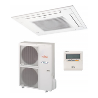
| Type | Split System |
| Outdoor Noise Level | 48 dB |