B 8 6
I
H
L
G
J K
S
T
N
M
OPQR
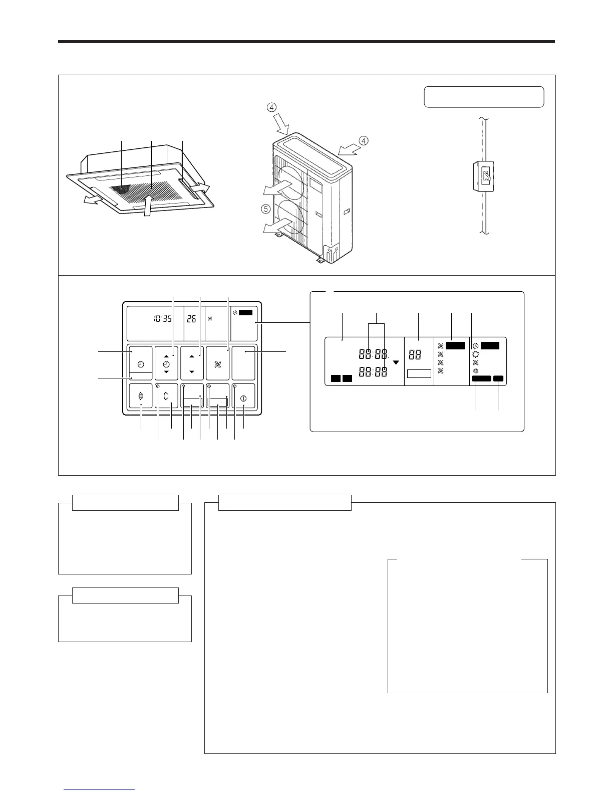
● For explanatory purposes, the figure showing the remote
controller display shows all possible displays. The actual
display shows only that area that is being adjusted or used.
Fig. 5 Display
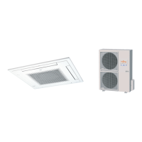
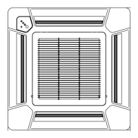
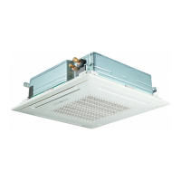
Fig. 1 Indoor Unit
1 Air Filter
2 Air Intake Grille
3 Air Flow Direction
Flaps
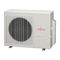
Fig. 2 Outdoor Unit
4 Air intake
5 Air outlet
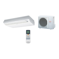
Fig. 4 Remote Controller
6 START/STOP Button
7 Operation Lamp
8 ENERGY SAVE Button
9 DAY OFF Button
0 ENERGY SAVE Lamp
A ZONE Control Button
B SET Button
C ZONE Control Lamp
D AIR FLOW DIRECTION SWING
Button
E AIR FLOW DIRECTION SWING
Lamp
F AIR FLOW DIRECTION SET Button
G CLOCK ADJUST Button
H TIMER MODE Button
I SET TIME Button
J SET TEMP./DAY Button
M Remote Controller Display
(Fig. 5)
N Ti mer Mode Display
O Clock Display (CLOCK/TIMER)
P Set Temperature Display
(TEMP.)
Q Fan Speed Display
R Operation Mode Display
S DEFROST Display
T TEST Display
Instructions relating to heating(*) are applicable only to “HEAT & COOL MODEL” (Reverse Cycle).
K FAN CONTROL Button
L MASTER CONTROL Button
13
2