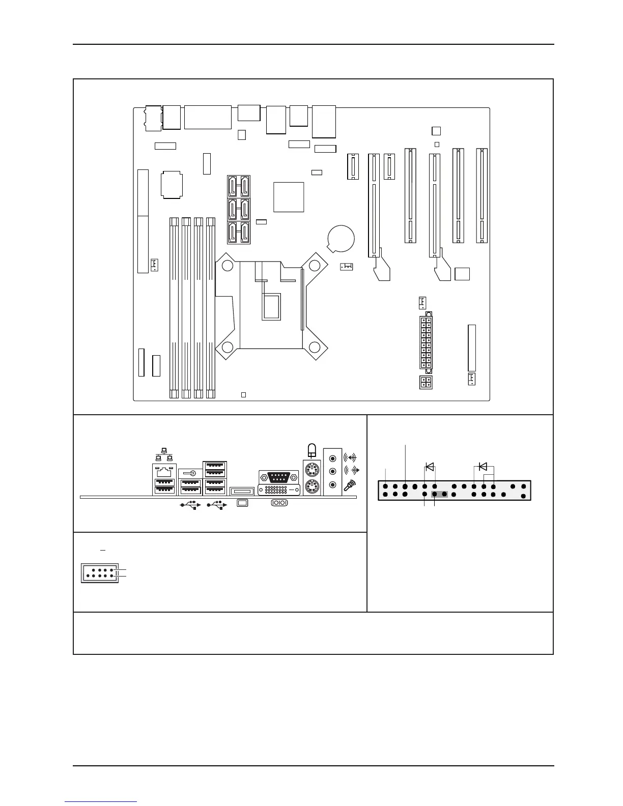
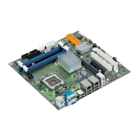
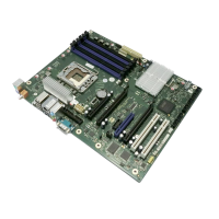
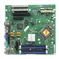
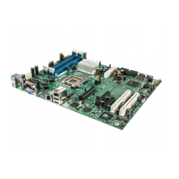
Internal connectors and slots
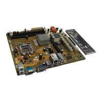
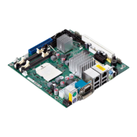
External connectors rear
USB dual channel
DVI-I
FW
1
2
1 = VCC AUX
2 = VCC AUX
3 = Data negative Port X
4 = Data negative Port Y
6 = Data positive Port Y
Data positive Port X
7 =
5 =
GND
8 = GND
9 = Key
10 = Not connected
A26361-D2917-Z240-1-8N19_2
Front panel
1) Both connector positions possible
2) 2pin or 3pin connector possible
1
2
HD-LED
Power On/Off
Recovery
1)
Reset
Power On
LED
2)
Recovery inserted = The system starts
from floppy and allows a BIOS recovery
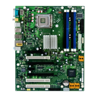
Module 4 Channel B
Module 2 Channel B
Module 3 Channel A
Module 1 Channel A
Battery
Audio PS2
COM1
DVI-I
Display
Port
USB
Port
11+1
USB
Port
9+10
LAN,
USB
Port 8+7
PCI2
PCI1
PCIe1
PCIe1
PCI3
PCIe4
Intrusion
FAN1
Temp.-
Sensor
FAN2
FAN1
Power
Supply 2
Frontpanel
Audio
Frontpanel
SATA
5+4
Intel-LAN
Firewire
SATA
3+2
SATA
1+0
CPU
LGA1156
Power Supply 1
USB Port
4+3
USB Port
FW intern
LCD-Connector
FAN 3
1+2
USB Port
PCH
1+3
Floppy Connector Parallel Port
PCIe16
Super
I/O
Temp.-
Sensor
FAN1: Front Fan CPU
FAN2: Front Fan Slotcards
FAN3: Heatsink CPU (optional)
Fujitsu Technology Solutions