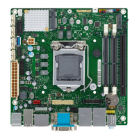
Internal connectors and slots
1
2
1 = 5V USB
2 = 5V USB
3 = Data negative Port X
4 = Data negative Port Y
6 = Data positive Port Y
Data positive Port X
7 =
5 =
GND
8 = GND
9 = Key
10 = Not connected
Front panel
USB 3.0
1 = 5V USB
2 = USB3_RX negative (P2)
3 = USB3_RX positive (P2)
4 = GND
USB3_TX negative (P2)
5 =
19
1
6 = USB3_TX positive (P2)
7 = GND
8 = Data negative (P2)
9 = Data positive (P2)
10 = FP Detect
11 = Data positive (P3)
12 =
Data negative (P3)
13 = GND
14 = USB3_TX positive (P3)
USB3_TX negative (P3)
15 =
16 = GND
17 = USB3_RX positive (P3)
18 = USB3_RX negative (P3)
19 = 5V USB
20 = Not connected
1
2
1 =
2 =
3 =
Audio Front Panel Connector
Mic Left
Mic Right
FP Present Detect
Headphone out Right
8 =
Analog GND
4 =
5 =
6 =
7 =
9 =
Jack Detect Mic
Analog GND
Key
Jack Detect Headphone
USB 2.0
External connectors rear
Recovery inserted = The system starts
from USB stick and allows a BIOS recovery.
Details can be found in the BIOS manual.
1
2
HD-LED
Recovery
Reset
Power
On/Off
Power LED
Channel A, Slot 1
USB 2.0
Front
Front
CPU
SATA 3
PWR 1
PS/ 2
USB 2.0
Display
Port
DVI-D / COM
LAN 2
FAN 1
LVDS Inv.
Buzzer
SPDIF
Frontpanel eDP Conn.
eDP Jump
.
PCH
COM2
Battery
Audio
SATA 2
Intrusion
LVDS
LVDS
Supply
LVDS Ctrl
..
GPIO
USB 3.0
FAN 2
PWR 2
USB 2.0 (2x)
LAN 2
USB 3.0 (2x)
SLOT 1 (PCIe x16)
M.2
SATA 0
miniPCIe
PCIe x1
D3434
Channel B, Slot 1
Audio Front
Panel Connector
Fujitsu