Do you have a question about the Fujitsu GENERAL AUHG18LVLB and is the answer not in the manual?
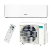
Technical specifications for AUHG18LVLB and AUHG24LVLA indoor units, including capacity, power, and noise levels.
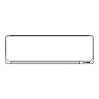
Detailed physical dimensions and diagrams for AUHG18LVLB and AUHG24LVLA indoor units.
Requirements for installing the indoor unit, including clearance and ceiling height considerations.
Electrical wiring diagram detailing connections for AUHG18LVLB and AUHG24LVLA indoor units.
Cooling capacity tables for AUHG18LVLB and AUHG24LVLA at various temperature and airflow conditions.
Heating capacity tables for AUHG18LVLB and AUHG24LVLA at various temperature conditions.
Airflow patterns and velocity distributions for different air outlet directions and fan speeds.
Airflow volumes (m³/h, l/s, CFM) for various fan speeds and ceiling modes.
Octave band sound pressure level curves for cooling and heating modes at different fan speeds.
Diagrams illustrating the microphone placement for measuring sound levels.
Protection mechanisms like fuses and thermal protection for fan motor and circuit.
Methods for remote operation using external switches or contacts for start/stop.
Outputting operation status and fresh-air control signals to external devices.
Explanation of the AR-RAH1E remote controller's buttons, display, and indicators.
Physical dimensions and weight of the remote controller and its holder.
Function settings configurable via DIP switches and jumper wires on the indoor unit PCB.
Procedures for setting functions using the remote controller, including custom codes.
List of accessories supplied with the indoor units, such as manuals, hose bands, and insulation.
Details on available optional wired and simple remote controllers.
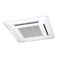
Information on optional cassette grille, connect kits, air outlet shutters, and LAN adapters.
Technical specifications for AOHG18LBCB and AOHG24LBCB outdoor units, including airflow, power, and refrigerant.
Physical dimensions and diagrams for the AOHG18LBCB outdoor unit.
Physical dimensions and diagrams for the AOHG24LBCB outdoor unit.
Required clearance and spacing for single outdoor unit installation.
Spacing requirements for multiple outdoor units in various side-by-side arrangements.
Spacing considerations for outdoor units installed in multiple rows.
Diagram illustrating the refrigerant flow path for the AOHG18LBCB model.
Diagram illustrating the refrigerant flow path for the AOHG24LBCB model.
Electrical wiring diagram detailing connections for the AOHG18LBCB outdoor unit.
Electrical wiring diagram detailing connections for the AOHG24LBCB outdoor unit.
Tables showing capacity compensation rates based on pipe length and height difference for AOHG18LBCB.
Tables showing capacity compensation rates based on pipe length and height difference for AOHG24LBCB.
Guidelines for calculating additional refrigerant charge based on total pipe length for both models.
Airflow volumes (m³/h, l/s, CFM) for cooling and heating modes for both outdoor units.
Octave band sound pressure level curves for outdoor unit cooling and heating.
Diagrams indicating microphone placement for measuring outdoor unit sound levels.
Power supply, frequency, operating current, and wiring specifications for outdoor units.
Protection mechanisms for outdoor units, including fuses and compressor/fan motor protection.
List of accessories supplied with the outdoor units, such as installation manual and drain pipe.
| Cooling Capacity | 5.0 kW |
|---|---|
| Refrigerant | R32 |
| Energy Efficiency Ratio (EER) | 3.5 |
| Power Supply | 230 V, 50 Hz |
| Type | Heat Pump |
| Energy Efficiency Ratio (Cooling) | 3.5 |