Circuit diagram example
Indoor unit
control PCB
Example: Switch
Locally purchased
Connected unit
1
3
Signal
*10 m
Connector
• Contact capacity: DC 24 V or more, 10 mA or
more.
• *: Make the distance from the PCB to the con-
nected unit within 10 m.
• Use non-polar relays and switches.
• When function setting is "Operation/Stop" mode
Operation
Stop
On
Off
Input signal
Indoor unit
• When function setting is "Forced stop" mode
Remote controller
On On On
Input signal
Indoor unit
Command
Remote control
operation invalidity
On
Off
Operation
Stop
Forced stop
Normal
Optional part
Part name Model name Exterior
External connect kit UTY-XWZX
External input wire
- 21 -
8-1. External input 8. External input and output
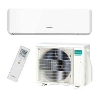
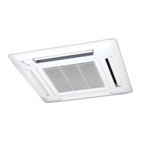
CASSETTE TYPE
AUHG18-24LVL
CASSETTE TYPE
AUHG18-24LVL
 Loading...