Preliminary 17(30)
Prepared Document Number
Manfred Ortmann
Approved Checked Date Revision Storage
2008-05-23 PA 6.2 Mycable01
Following table shows the assignment of LED, label and GPIO.
LED Label GPIO
D500 DIAG1 P25_0
D501 DIAG2 P25_1
D502 DIAG3 P25_2
D503 DIAG4 P25_3
Table 2-9: LED GPIO assignment
2.2.7 Serial Ports
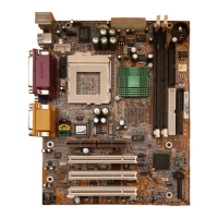
Pic. 2-11: Serial port connectors
UART 0 is available at the 9-pin Sub-D female connector X800 with RS-232 inputs and outputs.
UART 1 is available at the 9-pin Sub-D female connector X801 with RS-232 inputs and outputs.
As transceiver with enhanced electrostatic discharge ( ESD ) protection the MAX3243EIPW
( U800, U801 ) are used.
Following table shows the assignment of pins, signals and function from the UART connector
X800. Connector X801 is identical. For X801 the index 0 has to be changed to 1.
Pin Signal Function
1 RS232_0_CD Data carrier detect
2 RS232_0_TXD Transmit data
3 RS232_0_RXD Receive data
4 RS232_0_DSR Data set ready
5 GND Ground
6 RS232_0_DTR Data terminal ready