En-10
7.4. Connection of wiring
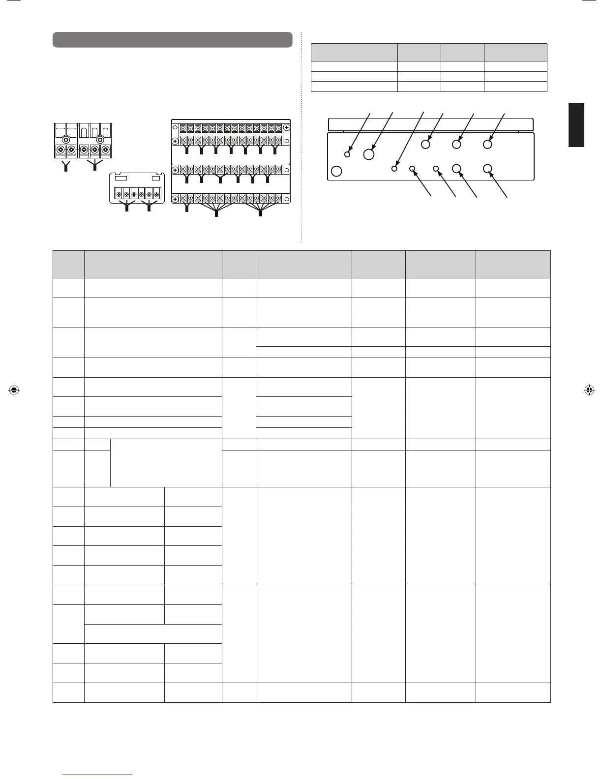
7.4.1. Terminal Explanation and Cable Holes
• Only one cable can be passed through each cable hole. To pass multiple cables
through a single cable hole, use a (fi eld supply) multi-conductor cable with more wires,
and bundle multiple cables into one.
• Maximum length of cable is 10 m. (recommended value, Except "P1" and "TR1")
TH1
TH2
TH3
TH4
EV1
EV2
EX1
EX2
EX3
EX4
EX6
EX7
EX5
EX8
EX9
EX10
P1
D1
TR1
R1
·Power supply terminal
·Drain pump signal terminal
·Transmission terminal
·Remote controller terminal
·External interface terminal
Cable holes with mounted cable glands (accessories)
Hole No.
Cable gland
type
Diameter
(mm)
Insertable cable
dimensions (mm)
H2 Large Φ20.0 Φ6 to 12
H5, H6, H7, H9, H10 Medium Φ16.2 Φ4 to 8
H1, H3, H4, H8 Small Φ10.2 Φ3 to 6
H1
H2
H3
H5
H4
H8
H9
H10
H6 H7
Terminal
No.
Terminal Name Hole No. Connection
Recommended
cable size
(mm
2
)
Cable type Specifi cations
P1 POWER SUPPLY H2 Power supply 2.5 (AWG14) Type245 IEC57 or
equivalent
1ø 50 Hz 198 to 264 V
2 Cable + earth (ground)
TR1 TRANSMISSION H3 Transmission line 0.33 (AWG22) LONWORKS compatible
cable
22 AWG LEVEL 4 (NEMA)
non-polar 2 core, twisted
pair solid core diameter
0.65 mm
R1 REMOTE CONTROLLER H4
2-wire type remote controller
0.33 to 1.25
(AWG22 to 16)
Sheathed PVC cable Non polar 2 core
3-wire type remote controller 0.33 (AWG22) Sheathed PVC cable Polar 3 core
D1 DRAIN PUMP H1 Drain pump 0.5 (AWG20) Type245 IEC57 or
equivalent
―
T1 THERMISTOR (GAS) H5 Thermistor mounted to the gas
pipe
0.33 (AWG22) Sheathed PVC cable Relay the multi-conductor
cable, and pass it through
the designated hole.
T2 THERMISTOR (LIQUID) Thermistor mounted to the liquid
pipe
T3 THERMISTOR (INLET AIR) Thermistor mounted to the inlet
T4 THERMISTOR (OUTLET AIR) Thermistor mounted to the outlet
EV1 EEV1 1 - Red
2 - Brown
3 - Black
4 - Green
5 - Yellow
6 - White
H9 Electronic expansion valve 1 0.33 (AWG22) Sheathed PVC cable ―
EV2 EEV2 H10 Electronic expansion valve 2 0.33 (AWG22) Sheathed PVC cable Use the electronic
expansion valves only
when two units are
connected
EX1 ON/OFF SIGNAL
(OUTPUT)
External output
/ Digital
H6 External controller 0.33 (AWG22) Sheathed PVC cable
―
EX2 ERROR SIGNAL
(OUTPUT)
External output
/ Digital
EX3 FAN SIGNAL External output
/ Digital
EX4 DEFROST SIGNAL External output
/ Digital
EX5 THERMOSTAT ON/OFF
SIGNAL
External output
/ Digital
EX6 ON/OFF SIGNAL (INPUT) External input
/ Digital
H7 External controller 0.33 (AWG22) Sheathed PVC cable ERROR SIGNAL
OFF(Open)= Error
ON(Short)= Normal
EX7* ERROR SIGNAL *
(INPUT)
External input
/ Digital
The factory default is shorted between the
terminals by the cables.
EX8 COOL/HEAT SIGNAL External input
/ Digital
EX9 ANALOG SIGNAL External input
/ Analog
EX10 FLOAT SW SIGNAL External input
/ Digital
H8 Float switch mounted to the heat
exchanger
0.33 (AWG22) Sheathed PVC cable
―
EX7*: The factory default is shorted between the terminals by the cables. If there is a malfunction with an external device, using this external input is recommended in order to protect the
refrigerant system.
9381279005_IM.indb 109381279005_IM.indb 10 6/30/2014 11:31:18 AM6/30/2014 11:31:18 AM
 Loading...