En-3
2.4. Optional parts
The following options are available.
When installing, refer to the installation manual of each optional part.
Connectable Peripheral Devices
Model Name Notes
Wired Remote Controller UTY-RNKY *1, *2
Wired Remote Controller UTY-RNRY *1, *2
Wireless Remote Controller
(IR receiver unit)
UTY-LNHY
(UTB-YWC)
*2
Group Remote Controller
(via network converter)
UTY-CGGY
(UTY-VGGXZ1)
*2
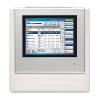
Touch Panel Controller UTY-DTGY *2
Central Remote Controller UTY-DCGY *2
Network Convertor for LONWORKS® UTY-VLGX *2
BACnet® Gateway UTY-ABGX *2
System Controller UTY-APGX *2
System Controller Lite UTY-ALGX *2
Service Tool UTY-ASGX *2
Web Monitoring Tool UTY-AMGX *2
Separation Tube (For EEV unit 2 connections) UTP-LX180A —
*1 Remote controller groups cannot be connected using DX-kits or other indoor units.
*2 If controlling using “external input and output” analog inputs from an external controller
(DDC), operations from the controllers described above are disabled.
3. PRODUCT SELECTION
• Failure to observe the selection conditions described below will affect the outdoor unit
service life and operational reliability.
• When selecting air handling unit, it must be designed for R410A refrigeration.
3.1. Product Lineup
(1) Product Lineup
Unit Name Model Name Environment specifi cations
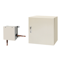
Control unit UTY-VDGX
• Temperature:
-20 to 46 °C
• Humidity:
10 to 90% RH
(No condensation)
EEV unit
UTP-VX30A
UTP-VX60A
UTP-VX90A
(2) EEV unit Selection
• The EEV unit is selected according to the capacity class conditions.
• If the capacity class is 40 kW or 50 kW, 2 EEV units are connected (in parallel).
Capacity Class (kW) 5.0 6.3 8.0 10.0 12.5
EEV unit model No.
30 30 30 60 60
Cooling capacity (kW)
5.6
6.3 8 10 12.5
Heating capacity (kW)
6.3
7.1 9 11.2 14
Heat exchanger capacity
Refer to the Design &Technical manual.
Airfl ow rate (Reference) (m
3
/h)
1,060
1,200 1,520 1,600 2,000
Capacity range Cool (kW) 5.1~5.9 6.0~7.1 7.2~9.0 9.1~11.1
11.2~13.2
Heat (kW) 5.7~6.7 6.8~8.0 8.1~10.0
10.1~12.4 12.5~15.0
Evaporation temperature Refer to the Design &Technical manual.
Condensation temperature Refer to the Design &Technical manual.
Capacity Class (kW) 14.0 20.0 25.0 40.0 50.0
EEV unit model No.
60 90 90 90+90 90+90
Cooling capacity (kW)
14
22.4 25 40 50.4
Heating capacity (kW)
16
25 28 45 56.5
Heat exchanger capacity
Refer to the Design &Technical manual.
Airfl ow rate (Reference) (m
3
/h)
2,240
3,560 4,000 6,400 8,000
Capacity range Cool (kW)
13.3~18.0 18.1~23.7 23.8~28.0 28.1~44.7 44.8~50.4
Heat (kW)
15.1~20.0 20.1~26.5 26.6~31.5 31.6~49.9 50.0~56.5
Evaporation temperature Refer to the Design &Technical manual.
Condensation temperature Refer to the Design &Technical manual.
Pipe size
(b)
(a)
(c)
(c)
(b)
(b)
(c)
(a)
(c)
(b)
Heat
Exchanger
Heat
Exchanger
Gas pipe Gas pipe
Liquid
pipe
Liquid
pipe
EEV
unit
EEV
unit
Capacity Class (kW) 5.0 6.3 8.0 10.0 12.5
Pipe size Gas (a) (mm) 15.88 15.88 15.88 15.88 19.05
Liquid (b) (mm) 9.52 9.52 9.52 9.52 9.52
Liquid (c) (mm) — ————
Capacity Class (kW) 14.0 20.0 25.0 40.0 50.0
Pipe size Gas (a) (mm) 19.05 22.2 22.2 28.58 28.58
Liquid (b) (mm) 9.52 12.7 12.7 12.7 15.88
Liquid (c) (mm) — — — 12.7 12.7
Pipe length
(a)
(d)
(c)
(f)
(e)
(b)
Heat
Exchanger
Heat
Exchanger
Gas pipe Gas pipe
Liquid
pipe
(a) ≤ 5 m (b) ≤ 2 m , (c) ≤ 2 m , (d) ≤ 2 m , (e) ≤ 2 m
(d) + (f) ≤ 5 m , (e) + (f) ≤ 5 m
Liquid
pipe
EEV
unit
EEV
unit
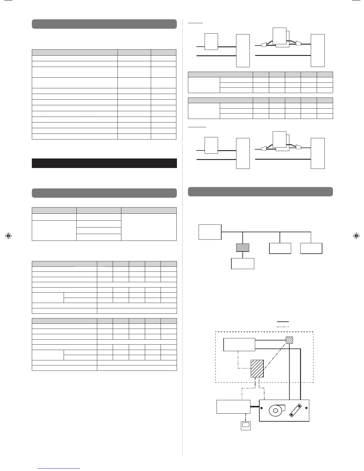
3.2. System Design
3.2.1. Basic Refrigerating System Confi guration
Using the DX-kit enables indoor units manufactured by other than Fujitsu general to be
used in the Fujitsu general refrigerant system.
DX-kit*
Outdoor unit
Indoor unit
Indoor unit Indoor unit
* DX-kit = Control unit + EEV unit
3.2.2. Basic DX-kit System Confi guration
(1) System Pattern 1
External controllers (DDC) not manufactured by Fujitsu general control the Fujitsu general
outdoor units and indoor units (refrigerant cycle devices, etc.) not manufactured by Fujitsu
general. With this system, control using a Fujitsu general VRF controller is not possible.
System Confi guration Diagram
Fujitsu general-approved devices
Outdoor unit
Indoor unit
Control unit
Liquid pipe
Gas pipe
Thermistor × 4
Wired remote
controller
External controller
not manufactured
by Fujitsu general
Control line
Piping
Wiring
EEV unit
For control line details, see “External Input and External Output”.
9381279005_IM.indb 39381279005_IM.indb 3 6/30/2014 11:31:17 AM6/30/2014 11:31:17 AM
 Loading...