En-16
8.2. Dip switch setting
(1) Capacity settings of indoor units to be controlled
The capacity of indoor units to be controlled is set.
Indoor unit
capacity
Dip switch setting (*: factory setting)
SET1-1 SET1-2 SET1-3 SET1-4 SET2-1
5.0 kW * ON OFF ON OFF OFF
6.3 kW ON OFF ON OFF ON
8.0 kW ON ON ON OFF OFF
10.0 kW OFF ON ON OFF ON
12.5 kW OFF ON OFF ON OFF
14.0 kW ON ON OFF ON OFF
20.0 kW ON OFF ON ON OFF
25.0 kW OFF ON ON ON OFF
40.0 kW ON OFF OFF ON ON
50.0 kW OFF ON OFF ON ON
Not described
above
Settings prohibited
(2) Setting digital input signal methods
• Select either edge method or pulse method as the external inputs signal method.
DIP switch SET2-2 Digital input signals format
OFF (factory setting) Edge
ON Pulse
Make sure that SET2-3 and SET2-4 are always OFF.
(3) Analog external inputs method
• You can select the item to be controlled using analog external inputs from the external
controller (either “Operation temperature” or “Required operation performance”).
• Make the DIP switch SET3-1 settings before making the SET3-2 settings.
• Make sure to set a connection status that uses the external controller.
• If SET3-1 is ON, VRF device controls will be disabled.
(i) Analog external inputs ON/OFF
DIP switch SET3-1 Analog external inputs ON/OFF
OFF (factory setting) OFF
ON ON
(ii) Control items
• The items to be controlled are selected according to the device status that uses the
external controller.
DIP switch SET3-2 Control conditions
OFF (factory setting) Operation temperature
ON Required operation performance
(4) AC (air conditioning.) control settings
• Select the AC control format from either “outlet temperature control” or “inlet temperature
control”.
DIP switch SET3-3 Temperature control position
OFF (factory setting) Outlet temperature control
ON Inlet temperature control
Make sure that SET3-4 is always OFF.
(5) RB unit bypass circuit feasibility
• If connecting the RB unit and a general indoor unit 1-to-1 in the heat recovery system
unit, confi gure a bypass circuit in the RB unit when the heat thermostat is OFF.
• Prevents hot air from outlet when the heat thermostat is OFF.
• If the indoor unit is 40kW or 50kW type, the RB unit cannot be connected.
DIP switch SET4-3
OFF (factory setting) No bypass
ON With bypass
(6) Administrative indoor unit setting
• You can set the DX-kit as the “administrative indoor unit” from among multiple indoor
units (including the DX-kit) connected using the same refrigerant system (or RB unit).
• Only one administrative indoor unit can be set using the same refrigerant system (or RB
unit).
If forming the remote controller group,set this DIP switch "OFF".
DIP switch SET4-4 Administrative indoor unit settings
OFF (factory setting) OFF
ON ON
• Precautions if using the DX-kit as the administrative indoor unit
If the ”Administrative indoor unit setting”is “ON” for another indoor unit connected to the
same refrigerant system (or RB unit), make sure to turn ”OFF” that setting. For details, see
the wired remote controller installation manual.
• When connecting the wired remote controller to the DX-kit, set this switch to OFF. (Set
the “Administrative indoor unit setting” with the wired remote controller.)
Make sure to set SET4-1 and SET4-2 to always OFF.
(7) Remote controller selections
The cable type of wired remote controller has been selected.
DIP switch SW1 Wired remote controller cable type
2WIRE (factory setting) 2 wire type
3WIRE 3 wire type
8.3. Function setting
• FUNCTION SETTING can be performed with the wired or wireless remote controller.
(The remote controller is optional equipment)
• Refer to the wired or wireless remote controller manual for detailed setting information.
(Set IU AD, REF AD SW to 0)
• Refer to “8.1. Setting the address” for indoor unit address and refrigerant circuit address
settings.
•
Turn the power of the indoor unit ON before starting the setting.
* Turning on the power to the indoor units initializes EEV, so make sure the piping air
tight test and vacuuming have been conducted before turning on the power.
* Also check again to make sure no wiring mistakes were made before turning on the
power.
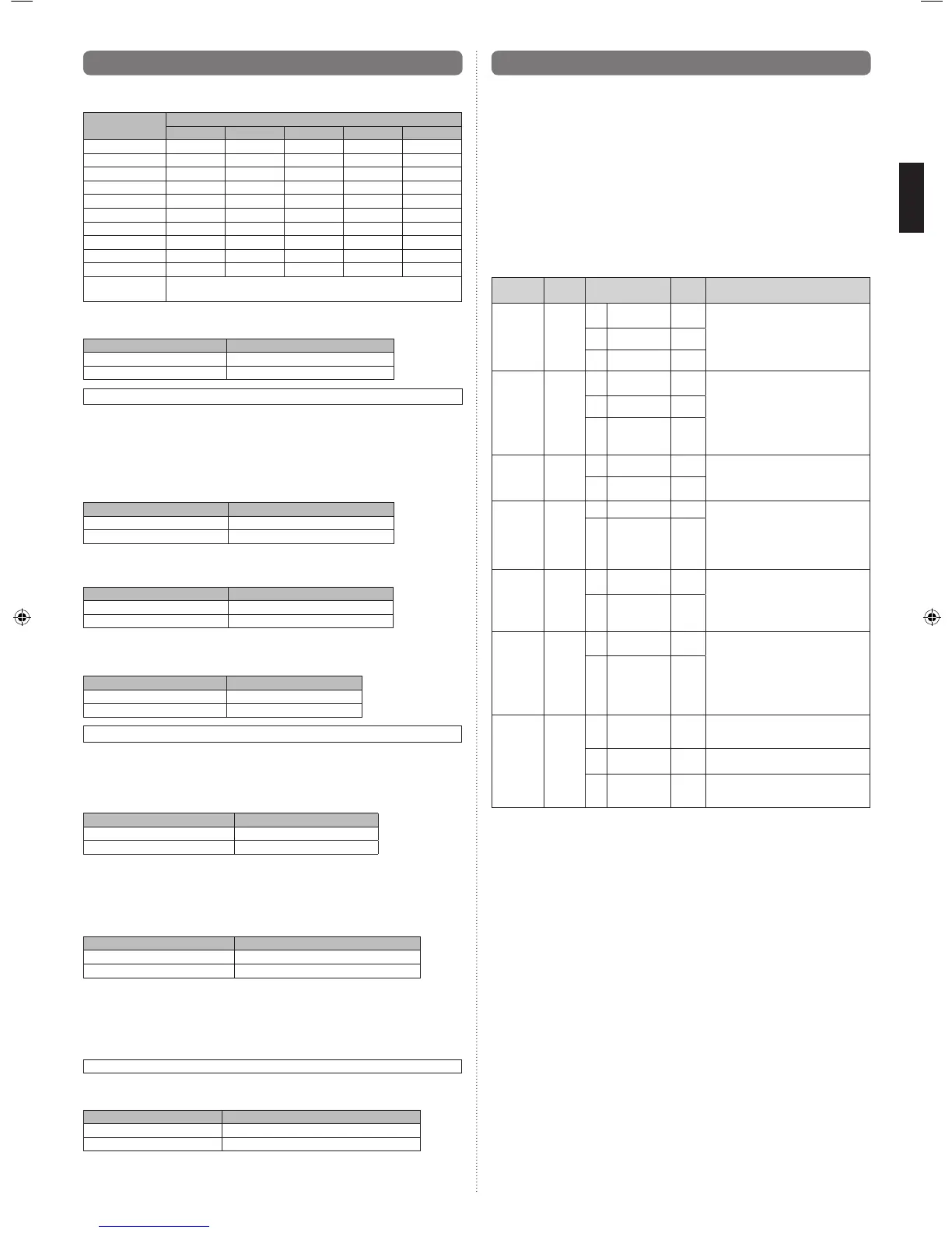
Function details
Function
Function
number
Setting number
Default
Details
Filter
indicator
interval
11
00 Standard
○
Adjust the fi lter cleaning interval notifi -
cation. If the notifi cation is too early,
change to setting 01. If the notifi cation
is too late, change to setting 02.
01 Longer
02 Shorter
Filter
indicator
action
13
00 Enable
○
Enable or disable the fi lter indicator.
Setting 02 is for use with a central
remote controller.
01 Disable
02
Display only on
central remote
controller
Auto
restart
40
00 Enable
Enable or disable automatic system
restart after a power outage.
01 Disable
○
Cool Air
Prevention
43
00 Super low
Restrain the cold airfl ow with making
the airfl ow lower when starting
heating operation.
If using Outlet temperature control
(DIP switch SET3-3: OFF) , set this
function"01".
01
Follow the
setting on
the remote
controller
○
Error report
target
47
00 All
○
Change the target for reporting errors.
Errors can either be reported in all lo-
cations, or only on the central remote
controller.
01
Display only on
central remote
controller
Switching
functions
for external
inputs and
external
outputs
terminals
60
00 Mode 0
○
The connection terminal functions can
be changed depending on the type
of external device. For details of the
connection terminal functions, see the
Design & Technical Manual.
01 Mode 1
Selecting
stop
operation
during an
external
error
64
00 Mode 0
○
Thermostat off
01 Mode 1 Thermostat OFF + fan stop
02 Mode 2
Thermostat OFF + fan stop + outdoor
unit stop
9381279005_IM.indb 169381279005_IM.indb 16 6/30/2014 11:31:18 AM6/30/2014 11:31:18 AM
 Loading...