En-4
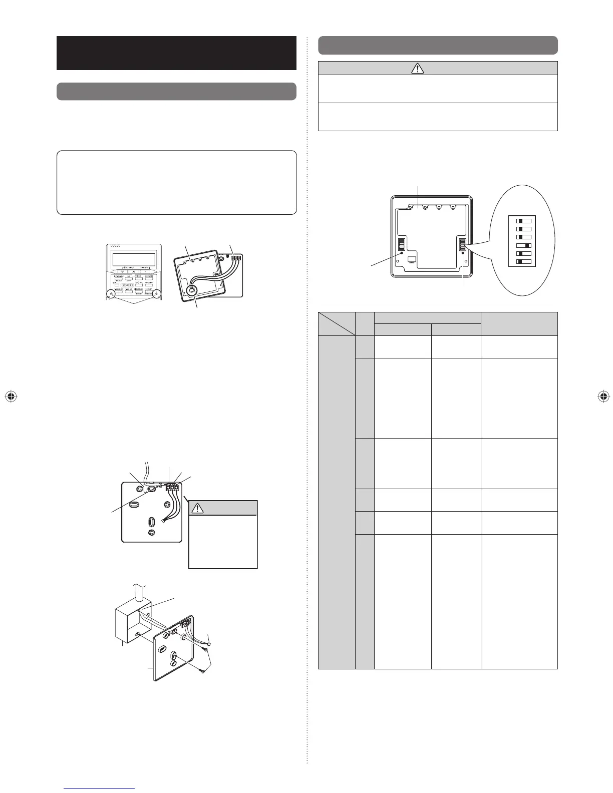
5.2. Setting the DIP switch
CAUTION
1
Install the remote controller wires so as not to be direct
touched with your hand.
2
Do not touch the remote controller PC board and PC
board parts directly with your hands.
Set the remote controller DIP switches.
Set DIP switch 1 - NO.6 to ON.
For the other switch, set it according to the situation.
[Example]
DIP switch 1
Front case (back side)
ONOFF
1
2
3
4
5
6
Do not use this
DIP switch 2
NO.
Switch state
Detail
OFF ON
DIP
switch 1
1
★
Cannot be used.
(Do not change)
2
★
Dual remote
controller setting
* Refer to 6.2.
Dual remote
control in 6.
INSTALLATION
METHODS.
3
★
Follow the
selection in
FUNCTION
SETTING
Invalidity
Filter reset
operation and fi lter
display
4
★
Cannot be used.
(Do not change)
5
★
Cannot be used.
(Do not change)
6
★
Invalidity Validity
Memory backup
setting
* Set to ON to use
batteries for the
memory backup.
If batteries are
not used, all
of the settings
stored in memory
will be deleted if
there is a power
failure.
(
★
Factory setting)
5. INSTALLING THE REMOTE
CONTROLLER
5.1. Installation
5.1.1. Installing the remote controller
Open the operation panel on the front of the remote controller,
remove the 2 screws indicated in the following fi gure, and
then remove the front case of the remote controller.
When installing the remote controller, remove the
connector from the front case. The wires may break if the
connector is not removed and the front case hangs down.
When installing the front case, connect the connector to
the front case.
Fig. 1
SET BACK
Front case
(back side)
Rear case
Screws
Connector
When remote controller cable is embedded
(1) Embed the remote controller cable and box.
(2) Pass the remote controller cable through the hole in the
rear case and connect the remote controller cable to the
remote controller terminal board specifi ed in Fig. 2.
(3) Clamp the remote controller cable sheath with the binder
as shown in Fig. 2.
(4) Cut off the excess binder.
(5) Install the rear case to the wall, box, etc., with 2 screws
(Fig. 3).
Fig. 2
Binder
CAUTION
1. Red
2. White
3. Black
Hole
▼
When connect-
ing the remote
controller
cables, do not
over tighten the
screws.
Fig. 3 [Example]
Remote controller
cable
Box
Screws
Connector
Rear
case
9373328148-02_IM_EN_FR_SP.indb 49373328148-02_IM_EN_FR_SP.indb 4 9/14/2010 1:15:27 PM9/14/2010 1:15:27 PM
 Loading...