Do you have a question about the Fukuda Denshi DS-7001 and is the answer not in the manual?
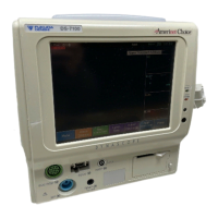
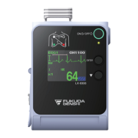
Details the DS-7001's compact design, lightweight, monitoring capabilities, and key features.
Illustrates the network connection example using the DS-7001 Bedside Monitor with central monitors.
Identifies and explains the functions of the main parts of the DS-7001 bedside monitor.
Lists standard accessories and items included in the NSK-506D Disposable Kit for NIBP and SpO2 monitoring.
Details optional accessories available for ECG, Impedance Respiration, NIBP, and SpO2 measurements.
Provides guidelines for environmental conditions, power source, and installation location for the DS-7001.
Explains how to connect the power cable and use the battery for operation.
Details the battery mark indicators, charging process, and charging duration.
Guides users through setting the device language upon initial power-on.
Explains setup for telemetry transmission, ON/OFF, and channel/group ID configuration.
Provides instructions and compatibility information for connecting ventilators to the DS-7001.
Covers precautions for handling the unit, display panel, storage, and cleaning the housing/transducer.
Details about the fuse location and replacement, and data backup battery replacement.
Describes handling, storage, and replacement of the battery pack.
Explains standard and forced install processes for upgrading the DS-7001 system software.
Details the function of each DIP switch and precautions for setting changes.
Outlines daily and periodic checks, and lists components requiring periodic replacement.
Explains how to access the 'Test Menu' by modifying DIP switch settings.
Details the procedure for testing the LCD display with various patterns.
Covers checks for analog board parameters, including A/D data for various signals.
Provides step-by-step instructions for adjusting ECG and Respiration waveform offsets.
Explains NIBP function tests, including measurement accuracy and AD display.
Details serial communication tests (SCI) and SpO2 unit communication status.
Covers system reset, demo mode operation, and CF card setup for hard copy recording.
Describes how to change the device language using the 'Test Menu'.
Lists components like LCD Unit, Lithium Battery, and Battery Pack with their replacement periods.
Details the need for LCD unit replacement due to usage hours or time, and its complexity.
Provides step-by-step instructions for replacing the data backup lithium battery.
Guides users on replacing the battery pack after 2 years or 300 charge/discharge cycles.
Addresses issues like ECG noise, no heart rate count, lead off, and pacemaker display problems.
Covers NIBP cuff inflation issues, error messages, and SpO2 waveform or value problems.
Troubleshoots alarm generation, telemetry communication, and waveform display anomalies.
Addresses general system issues like test mode display, clock errors, and battery charging problems.
Covers CF card recording errors, status messages, and startup error diagnoses.
Details the physical dimensions, weight, operating/storage environmental conditions, and safety standards.
Lists display panel specifications, input/output, and performance metrics for ECG, Respiration, and NIBP.
Defines default and backup settings for patient admit, alarm, and parameter configurations.
Details system configuration for tone/volume, colors, lamps, and preset menu options.
Explains the pin assignments for the I/O port used for external connections.
Shows the block diagram illustrating the basic composition and wiring of the DS-7001 system.
Explains the functions of the CPU board components like CPU, Flash Memory, SRAM, and Gate Arrays.
Details the analog board's role in signal conversion and measurement control for ECG, NIBP, and SpO2.
Provides general specifications for the SpO2 units used with the DS-7001.
Explains the circuits of the NIBP amplifier board and NIBP drive unit.
Details the power supply board functions and the telemetry transmitter unit circuits.
Describes the LED board's connection to the CPU board and the function of its LEDs.
| Brand | Fukuda Denshi |
|---|---|
| Model | DS-7001 |
| Category | Medical Equipment |
| Language | English |