Do you have a question about the Fukuda Denshi FX-2111 and is the answer not in the manual?
Explanation of warning symbols used in manuals and on the instrument.
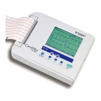
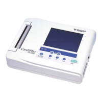
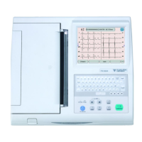
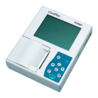
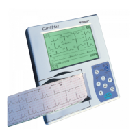
Description of the FX-2111 as an easy-to-use single-channel electrocardiograph.
Details of the FX-2111's technical specifications, including ECG and general parameters.
Description of controls and indicators on the top panel of the FX-2111.
Details of input/output terminals on the left and right side panels.
Description of battery room and fuse holders on the bottom panel.
Details on the buffer amplifier, lead selector, and signal isolation circuits.
Explanation of power supply generation and battery charging mechanisms.
Overview of the CPU, ROM, RAM, and gate array functions.
Guidance on diagnosing and resolving problems with power supplies.
Troubleshooting steps for charging mode and status issues.
Troubleshooting procedures for abnormal LCD operation and key input failures.
Procedures for replacing power fuses, ROM, and rechargeable battery.
Instructions for performing self-tests to check instrument functions.
List of system error codes, their types, and descriptions.
Guidelines and precautions for disassembling and reassembling the instrument.
Methods for measuring leakage current and protective grounding resistance.
High-level block diagram illustrating the FX-2111's system architecture.
Detailed schematics for the main board, covering various sections.
Circuit diagrams for power, sensor, motor, and battery pack modules.
Illustrations showing the assembly of the main board components.
Exploded views and assembly details for the unit's cases and major sub-assemblies.
List of major blocks and assemblies for the FX-2111.
Detailed parts list for the main board, including resistors, capacitors, and ICs.
Parts list for AC inlet boards and the LCD assembly.
Spare parts list for PCBs, fuses, nuts, and washers.
Spare parts list for recorder components, cases, and screws.
Diagrams showing the external views and overall dimensions of the FX-2111.
Exploded views detailing the arrangement of internal components.
| Type | Electrocardiograph |
|---|---|
| Display | LCD |
| Printing Method | Thermal Printing |
| Channels | 3-channel, 6-channel |
| Recorder | Thermal Array |
| Power Source | AC |
| Power Supply | 100-240V AC, 50/60Hz |
| Operating Environment | Temperature: 10°C to 40°C, Humidity: 30% to 85% (non-condensing) |
| Storage Environment | Humidity: 25 to 95% RH (non-condensing) |