Do you have a question about the Fukuda Denshi FX-7302 and is the answer not in the manual?
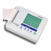
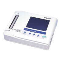
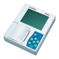
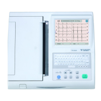
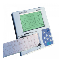
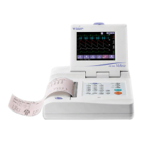
Identifies components on the top of the unit, including display and operation panel.
Details ports and compartments on the unit's sides, rear, and bottom.
Explains the controls and indicators on the unit's front operation panel.
Lists technical specifications for leads, sensitivity, power, dimensions, and environment.
Provides instructions on how to clean the unit safely, avoiding damage from chemicals.
Step-by-step guide for safely removing and installing the unit's battery pack.
Describes the procedure for updating the unit's software using a CF card.
Instructions for installing optional software cartridges into the unit.
Details user and manufacturer self-diagnostics tests for system checks and adjustments.
Outlines required periodic inspections, intervals, precautions, and specific tests for safety and performance.
Step-by-step guide for safely removing the unit's outer enclosure cover.
Instructions for removing the main and ECG amplifier boards, emphasizing static precautions.
Procedure for safely detaching and removing the recorder unit from the main assembly.
High-level overview of the unit's main functional blocks and their interconnections.
Detailed block diagram of the main board, showing major sections like CPU, memory, and peripherals.
Block diagram illustrating the ECG amplifier board's input, amplification, and conversion stages.
Block diagram of the operation board, detailing LCD contrast and backlight control circuits.
Block diagram of the power board, showing voltage generation and distribution for the unit.
Detailed circuit schematics for the main board, including power connection tables.
Circuit diagram detailing the interface and control logic for the CF card reader.
Circuit diagram for the RS-232 serial port driver and signal conditioning.
Circuit diagram for the interface between the keypad, LCD, and main CPU.
Circuit diagram for sensor inputs, speaker output control, and JTAG interface.
Circuit diagram illustrating the network interface and control for LAN connectivity.
Circuit diagram detailing the power-on sequence and control logic for the unit.
Lists part numbers, configurations, and specifications for the main board components.
Lists part numbers and specifications for components on the ECG amplifier board.
Lists part numbers and specifications for components on the operation board.
Lists parts for the mark sensor and magazine up sensor boards.
Lists parts for the connection board, including connectors.
Lists miscellaneous spare parts not categorized under specific boards.
Illustrates the layout of components on the component side of the main board.
Illustrates the layout of components on the soldering side of the main board.
Shows the component layout on the component side of the operation board.
Shows the component layout on the component side of the ECG amplifier board.
Shows the component layout on the component side of the connection board.
Exploded view and parts list for the first section of the recorder assembly.
Exploded view and parts list for the second section of the recorder assembly.
Exploded view and parts list for the third section of the recorder assembly.
Exploded view and parts list for the fourth section of the recorder assembly.
Exploded view and parts list for the ECG amplifier unit assembly.
Exploded view and parts list for the upper case assembly.
Exploded view and parts list for the lower case assembly.
Overall exploded view showing how major assemblies fit together.
Shows external dimensions and views of the unit.
Declaration regarding the equipment's electromagnetic emission characteristics according to CISPR11.
Declaration of electromagnetic immunity levels for ESD, transients, surges, voltage variations.
Declaration of electromagnetic immunity levels for conducted and radiated RF.
Guidelines for maintaining safe separation distances from RF communication devices.
Information on how the equipment handles interference from electrosurgical devices.
| Type | Electrocardiograph |
|---|---|
| Display | LCD |
| Printing Method | Thermal |
| Power Source | AC power or rechargeable battery |
| Operating Conditions | Temperature: 10 to 40°C, Humidity: 30 to 85% RH |
| Storage Conditions | Humidity: 25 to 95% RH (non-condensing) |