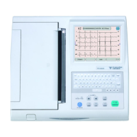
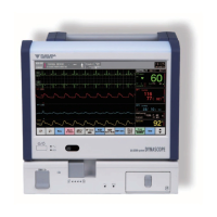
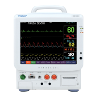
Do you have a question about the Fukuda Denshi VaSera VS-1500 and is the answer not in the manual?
Explains the meaning of DANGER, WARNING, CAUTION, and NOTE labels.
Explains the meaning of graphic symbols indicating prohibition or compulsion of acts.
Provides information on the features of this equipment.
Provides information on the specifications of this equipment.
Lists the name, model type, and function of accessories and optional accessories.
Describes the location and function of the instrument's parts.
Explains maintenance, cleaning, self-diagnosis, and installation procedures.
Explains how to resolve problems for each symptom.
Lists onscreen messages and provides information on countermeasures.
Describes procedures for disassembling and assembling the instrument.
Provides wiring diagrams, block diagrams, and connector pin locations.
Details part locations and critical checkpoints for troubleshooting.
Lists the spare parts of this equipment.
Explains information concerning the electromagnetic compatibility (EMC) of the VS-1500.
Lists reference data such as connector signal arrangement.
Overview of the instrument's capabilities and functions.
Details the primary functions and measurements the instrument performs.
Highlights key and advanced functionalities of the instrument.
Describes the different modes available for conducting examinations.
Provides detailed technical specifications for the VS-1500N model.
Lists all standard and special accessories included with the VS-1500N.
Lists accessories that are available as optional additions.
Identifies and describes components on the front panel of the instrument.
Identifies and describes components on the rear panel of the instrument.
Identifies and describes components on the bottom of the instrument.
Details the layout and function of the instrument's operation panel.
Procedure for replacing the internal battery that maintains clock and settings.
Instructions for cleaning and disinfecting the instrument and its accessories.
Guides users through diagnostic tests for instrument status and parameters.
Provides advanced diagnostic functions for manufacturer-level maintenance.
Details procedures for installing software and upgrade packages.
Procedure to optimize the thermal print head and chart paper of the recorder.
Explains maintenance procedures for the connected VSP-15 color printer.
Troubleshooting steps for power supply issues affecting instrument startup.
Troubleshooting steps for problems with the built-in thermal array recorder.
Troubleshooting steps for blood pressure measurement errors.
Troubleshooting steps for ECG lead and signal related issues.
Troubleshooting steps for PCG and pulse wave measurement problems.
Troubleshooting steps for issues with fixed keys or the touch panel.
Troubleshooting steps for display malfunctions.
Troubleshooting steps for CF card related errors.
Troubleshooting steps for LAN communication problems.
Troubleshooting steps for issues with the connected color printer.
Troubleshooting steps for serial communication errors.
Troubleshooting steps for other instrument functions like date/time and buzzer.
Lists onscreen messages and provides information on countermeasures.
Lists messages related to the instrument and its measurements.
Lists messages specific to CF card operations.
Lists messages related to the color printer.
Lists messages related to PC communication.
Provides instructions for disassembling the instrument.
Step-by-step guide to removing the upper and lower cases.
Procedure for removing the main board from the instrument.
Instructions for removing the pump block assembly.
Procedure for removing the recorder and power supply unit.
Step-by-step guide to removing the LCD unit.
Instructions for removing the keyboard.
Provides instructions for assembling the instrument.
Procedure for assembling the main block.
Illustrates the assembly steps for the lower case.
Provides the assembly drawing for the LCD unit's rear components.
Provides the assembly drawing for the upper case of the instrument.
Presents the overall assembly drawing of the instrument.
Instructions for assembling the OTV-01 trolley.
Instructions for installing the OAV-01A cuff holder.
Instructions for installing the OAV-03A printer shelf.
Instructions for installing the OA-300A cable hanger.
Instructions for installing the OA-130 hose hanger kit.
Explains the symbols used in wiring and block diagrams.
Shows the wiring connections between internal components.
Provides block diagrams and descriptions of the instrument's main functional blocks.
Lists the pin arrangements for various connectors on the instrument.
Details the part location diagram and checkpoints for the main board.
Details the part location diagram and checks for the cuff board.
Details the part location diagram and checks for the LCDTP IF board.
Details the power supply unit.
Lists parts and accessories requiring periodical inspection and replacement.
Provides a parts list for the main unit of the instrument.
Provides a parts list for the upper case block.
Provides a parts list for the LCD block.
Provides a parts list for the lower case block.
Provides a parts list for the pump block.
Provides a parts list for the main block.
Provides a parts list for the LCD unit.
Shows part block diagrams for the instrument.
Lists standard accessories for the VS-1500N.
Lists optional accessories available for the instrument.
Lists consumable items such as NIBP cuffs and paper.
Provides guidance on electromagnetic compatibility and usage environments.
Details the instrument's electromagnetic emission characteristics.
Describes compatibility with electromagnetic immunity standards.
Details compatibility with electromagnetic immunity standards.
Specifies separation distances for RF equipment to prevent interference.
Addresses interference from electrical scalpels.
| Brand | Fukuda Denshi |
|---|---|
| Model | VaSera VS-1500 |
| Category | Medical Equipment |
| Language | English |
