4
ESPAÑOL
ENGLISH
PORTUGUÊS
6 - SINALIZAÇÕES
REFRIG - Saída de refrigeração ligada
DEFROST - Realizando degelo natural
[err] - Sensor desconectado ou temperatura fora da faixa especicada
[OFF] - Funções de controle desligadas
[def][,On] - Acionamento manual do processo de degelo
[def][OFF] - Acionamento manual do processo de refrigeração
[LOC][,On] - Bloqueio de teclas
[LOC][OFF] - Desbloqueio de teclas
7 - SELEÇÃO DE UNIDADE (ºC / ºF)
Para denir a unidade que o instrumento irá operar entre na função “F01” com o código de acesso
231 e conrme na tecla @. Pressione a tecla < e aparecerá a indicação [Uni].
Pressione @ Para escolher entre [,=C] ou [,=F] e conrme. Após selecionar a unidade
aparecerá [faC] e o instrumento voltará para a função “F01”. Toda a vez que a unidade for
alterada os parâmetros devem ser recongurados, pois eles assumem os valores “padrão”.
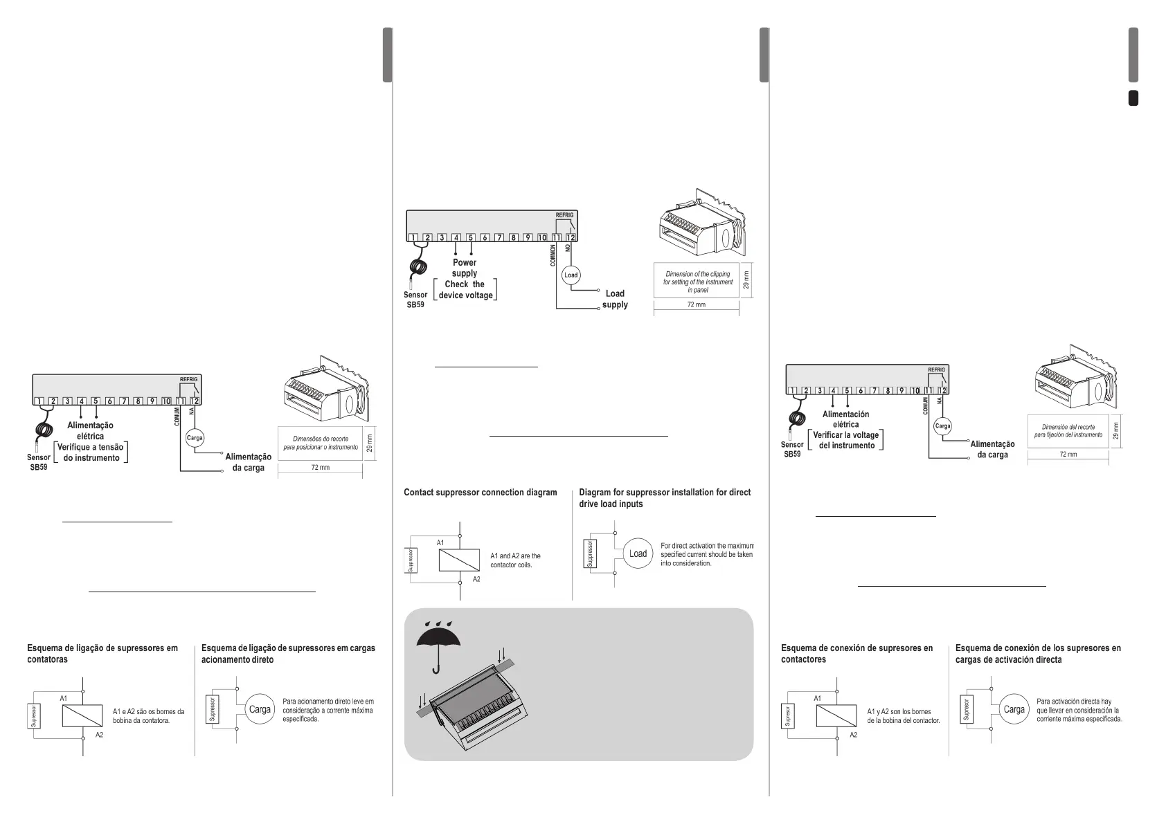
8 - ESQUEMA DE LIGAÇÃO
IMPORTANTE
Conforme capítulos da norma NBR 5410:
1: Instale protetores contra sobretensões na alimentação.
2: Cabos de sensores e de comunicação serial podem estar juntos, porém não no mesmo eletroduto
por onde passam alimentação elétrica e acionamento de cargas.
3: Instale supressores de transientes (ltro RC) em paralelo às cargas, como forma de aumentar a
vida útil dos relés.
A Full Gauge Controls disponibiliza supressores para venda
Nota: O comprimento do cabo do sensor pode ser aumentado pelo próprio usuário, em até 200
metros, utilizando cabo PP 2 x 24 AWG. Para imersão em água utilize poço termométrico.
instrumento”.
IMPORTANT
According to the chapters of norm IEC 60364:
1: Install
protector against overvoltage
on the power supply.
2: Sensor cables and signal cables of the computer may be joined, but not in the same electric conduit
through which the electric input and the activation of the loads run.
3: Install transient suppressors (RC lters) parallel to the loads as to increase the product life of the
relays.
Suppressors on offer from Full Gauge Controls
Note: The length of the sensor cable may be increased by the user up to 200 meters, using a PP 2
x 24 AWG cable. For immersion in water, use thermometric well.
[LOC][OFF] - Keypad unlocked
7 - SELECTION OF THE UNIT (ºC / ºF)
In order to dene the unit that the instrument will operate in, enter function “F01” with the access
code 231 and conrm with the @ key. Press the < key and the indication [Uni] will appear.
Press @ to choose between [,=C] or [,=F] and conrm. After selecting the unit the [faC]
message will appear, and the instrument will return to the function “F01”. Every time that the unit is
changed, the parameters should be recongured, since they assume the “standard” values.
8 - WIRING DIAGRAM
[def][OFF] - Activation of refrigeration cycle manually
[LOC][,On] - Keypad locked
Nota: El propio usuario puede aumentar la longitud del cable del sensor hasta 200 metros,
utilizando un cable de PP 2 x 24 AWG. Para inmersión en agua utilice pozo termométrico.
6 - SENÃLIZACIONES
REFRIG - Salida de refrigeración conectada
DEFROST - Realizando deshielo natural
[err] - Sensor desconectado o temperatura fuera del rango especicado.
[OFF] - Funciones de control desconectadas
[def][,On] - Activación manual del proceso de deshielo
[def][OFF] - Activación manual del proceso de refrigeración
[LOC][,On] - Bloqueo de teclas
[LOC][OFF] - Desbloqueo de teclas
7 - SELECION DE LA UNIDAD (ºC / ºF)
Para denir la unidad con que el instrumento operará, acceda a función “F01” con el código de
acceso 231 y conrme en la tecla @. Presione la tecla < y aparecerá la indicación [Uni].
Presione @ para elegir entre [,=C] y [,=F] conrme. Después de seleccionar la unidad
aparecerá [faC] y el instrumento volverá a la función “F01”. Cada vez que la unidad sea
alterada, los parámetros deben ser recongurados, ya que ellos asumen los valores “estandar”.
8 - ESQUEMA DE CONEXIÓN
IMPORTANTE
Conforme capítulos de la norma IEC 60364:
1: Instale protectores contra sobretensiones contra sobretensiones en la alimentación.
2: Los cables de sensores y de señales de computadora pueden estar juntos; sin embargo, no en
el mismo electroducto por donde pasa la alimentación eléctrica y la activación de cargas.
3: Instale supresores de transientes (ltros RC) en paralelo a las cargas, con la nalidad de
aumentar la vida útil de los relés.
Full Gauge Controls posee supresores para venta
funciones “F06 - Retardo para reconectar la salida de refrigeración” y “F09 - Estado inicial al
reconectar el instrumento”.
PROTECTIVE VINYL
This adhesive vinyl (included inside the packing) protects
the instruments against water drippings, as in commercial
refrigerators, for example. Do the application after
nishing the electrical connections.
Remove the protective paper and apply the vinyl on the
entire superior part of the device, folding the aps as
indicated by the arrows.
 Loading...