Ch a pte r 3 M e cha n ic al and Elec t rical Insta l la t i o n
3.1
Mecha nic al In st all atio n
1)A mbient te m perat ure: Am bient tempe rat ur ein fluenc es the inverter li f e greatly, s o itsh oul d b e within
t he range of -10 ~50 .
2) Moun t th e i nv erter in a flame retardant s urf ace andth e clearanc e around the inve rt er s h a ll be en oug h
be cause the i nverter will generate l ots of heat d uring ru nning, be s ides moun t the invert er on the base
vertically with screws.
3) Mo unt i n th e loca ti on w he re vi brat i on is l e ss t han 0. 6G; th e inve r te r s ha ll b e f ar away f r om imp act in g
lathe.
4) Please do no t inst all the inver ter in t he pl ac ew it h dir ect s u nlight, high humid itya nd w ater.
5) Mount the i nverte r int h e loca tio n f re eof corro s iveg as, e x plosive gas or comb ust iblega s.
6) Mount t he i nverte r in t h e loca tio n f re eof oildir t, dust, and met a l pow der.
1.I nstall ation Envi ronment
2 .Insta llation Lo c a ti on
℃℃
DZB
up
right
A
≥100mm
≥100mm
A
DZB
DZB
Note: No need to consider the dimensio n
Afor inverter of22k W orbelow.
Asha ll bebigger tha n50 mm forthe
i nvert er of 22 kW or above
Note : Installan airflow- guidance
plate for the up and down instal lation
of inverters.
Fig.3-1D ZB SeriesInverter Installation Location
The user s hall f o cus o n the h eat d issipat ionis sues when install ing t h einve rter, an d pay att e ntion to the
fo llowing points:
1) In stall th e inv e rter vertic a lly so tha t the heat ma y be expelle d f rom the top, but d o n ot install th e
inve r ter upside down. When two Variab le Sp eed D rives a r e mo unted up an ddow n, an air fl ow
divertingplateshouldbefixedinbetweenasshowninFig.3-1.
2)Ins tallat ion space i s show n in Fig.3- 1 so as to en sure t he heat diss ipation spa ce, bu t cons ider th e
heat d issipation ofoth ercom pone nts w hen placing t he in verte r.
3) Theinst allati onbracket m ustbe flame retardant.
4) Ins tall the heat sink outsi de of the c abinet if the invert eris i nstall ed in the are a wi th met al powder.
And inthis case, the s p ace i n side the s e aling c abinetshal l be b i g eno ugh.
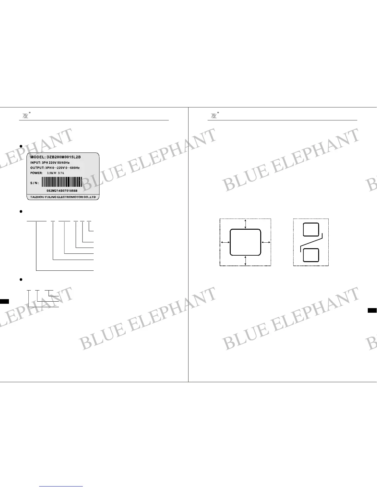
Nameplate
DZB200
M
0015
L
2B
Function levelcode: A-braking unitinside
B -non braking unit
Input voltage
Freq.Ran ge
Applicab le mot or capacity
Series M Model
Model
Seriesna me Series
2-220V 4-400V 6-660V
L 0-600.0H z
0015 1.5KW
:Mini
J:Simpl
:DZB200
:
::
:为
:
Des cription ofACMotor Drive Model:
P roducti on numbe r
Productionmonth
Productionyea r
88880107
Des cription of Serial Numbe r:
2.2 Na meplate Information
-7- -8-
Install ation of single inverte r Up and down i nstallation o f inve r ters
Chapter 2 Prod uct Introduction
DZB Series
Cha pt er 3 M e ch anic al and Electri cal Instal lation
DZB Series
BLUE ELEPHANT
BLUE ELEPHANT
BLUE ELEPHANT
BLUE ELEPHANT
BLUE ELEPHANT
BLUE ELEPHANT
BLUE ELEPHANT
BLUE ELEPHANT
BLUE ELEPHANT
BLUE ELEPHANT
BLUE ELEPHANT
BLUE ELEPHANT
BLUE ELEPHANT
BLUE ELEPHANT
BLUE ELEPHANT
BLUE ELEPHANT
BLUE ELEPHANT
BLUE ELEPHANT
BLUE ELEPHANT
BLUE ELEPHANT
BLUE ELEPHANT
BLUE ELEPHANT
BLUE ELEPHANT
BLUE ELEPHANT