0: Terminal c ommandinval id w hen power on. Inverte r wi llnot runi f itd etect operating command terminal
i sva lid.W hen t he operating command terminal is invalid and en able this ter minal again, i nverter will run.
1: Te rm in al c om man d va li d whe n po we r on. Inver ter w il l sta r tup automa tically a fte r initi al iz ation is
finishedif i t det ect operation command terminal is valid.
Note: Customer s houldbecareful when youselect this function, it may cause severe co nsequence.
Chapter 6 Parameter D escripti on
DZB Series
-42-
F 1 Motor Para meter s
F1.00 Reserved
Fu nction
Code
Name
Settin g Range
Default
Value
F1.01
Mot or ra t ed po wer
0.4 55 .0kW
~
50. 00Hz0.0 1Hz F0.04
~
Motor rated frequency
0 9999rpm
~
Motorratedspeed
0460V
~
Mot or ra t ed v oltage
0.1 10 0.0A
~
Motor rated current
F1.02
F1.0 3
F1. 04
F1.05
Set by
model
Set by
model
Set by
model
Set by
model
0.0 01 9.999
~Ω
M o tor stator resis tan ce
F1.0 6
Set by
model
F1.07
M ot o r ro t or re si st ance
0.0 01 99.99
~Ω
F1.08
M o tor stator/roto r
in duct ance
0.1 99 9.9mH
~
Setby
model
Setby
model
F1.09
Mutual inductance o f
m o tor stator/roto r
0.1 99 9.9mH
~
F1.1 0
No -load cu rrent
0.01 99.99A
~
Setby
model
Setby
model
F1.11
Se lf-lea rning of
mot or para meters
0 NO ope ration
:
1 Sel f-learning
:
comp lete tuning
2
:
sta tic tuni n g Self-l earn ing
0
F1.12
Sp eed loop propor tion al
gain1
0100
~
30
F1.1 3
Sp eed loop integral t i me1
0.01 10.00s
~
0.50s
F1. 14
Switching l ow
po int f requenc y
0.0 0Hz F1.1 7
~
5.00Hz
F1.15
Sp eed loop propor tion al
gain 2
0100
~
25
F1.1 6
Speedloopintegral
time 2
0.01 10.00s
~
1.0 0s
F1.17
Switching hi gh
po int f requenc y
F1. 14 9 9.99Hz
~
10. 00Hz
F1.18
VC slip compen sa ting
factor
50 % 2 00%
~
10 0%
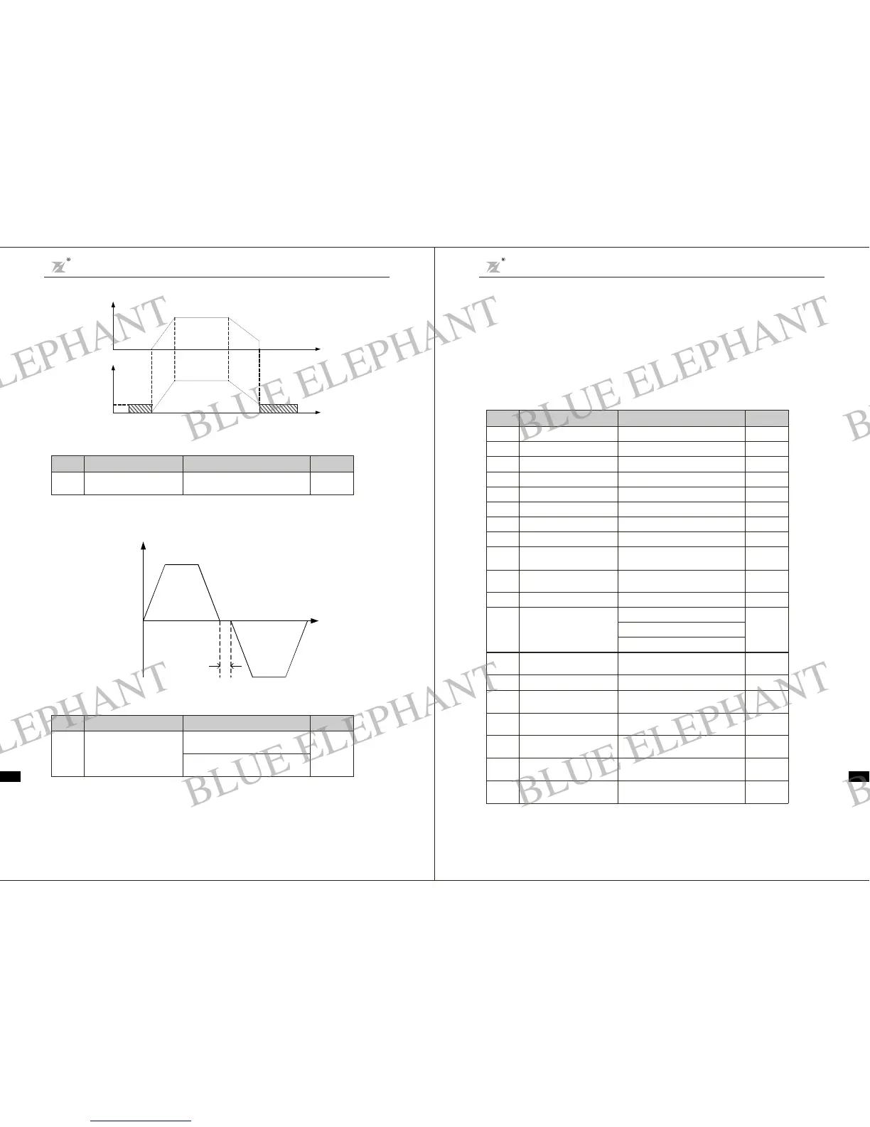
I t is t o set th e transie n t ti m e dur ing whic h the o u tput f req uen c y i s 0 in th e F WD/REV tran si e nt proc ess
of inverter.
It is s hown as following figure:
F ig. 6-3DC Brake Diagram
Fig. 6-4FWD/REV Dead Time Diagram
If operating command channel is set to terminal control, systemwi ll detect terminal status
au tomatically during inverter power on.
OutputFrequencyf
Output
Voltage
Timet
DCBrake
when
stopping
Timet
DCBrake
when
starting
Outp ut
Frequency f
Forward
Re ver se
Dea d Time
Time t
F0.24
Dead t ime be tween
forward and r everse
0.0 360.0s
~
0.0s
Funct ion
Code
Nam e
SettingRange
Default
Valu e
F0. 25
Terminal command
prote ction w hen
pow er on
0 Term inal c om mand i nva lid
wh en pow er on
:
1 Term inal command vali d when
pow er on
:
0
Funct ion
Code
Nam e
SettingRange
Default
Valu e
Chapter 6 Parameter Descr iption
DZB S eri es
-41-
BLUE ELEPHANT
BLUE ELEPHANT
BLUE ELEPHANT
BLUE ELEPHANT
BLUE ELEPHANT
BLUE ELEPHANT
BLUE ELEPHANT
BLUE ELEPHANT
BLUE ELEPHANT
BLUE ELEPHANT
BLUE ELEPHANT
BLUE ELEPHANT
BLUE ELEPHANT
BLUE ELEPHANT
BLUE ELEPHANT
BLUE ELEPHANT
BLUE ELEPHANT
BLUE ELEPHANT
BLUE ELEPHANT
BLUE ELEPHANT
BLUE ELEPHANT
BLUE ELEPHANT
BLUE ELEPHANT
BLUE ELEPHANT