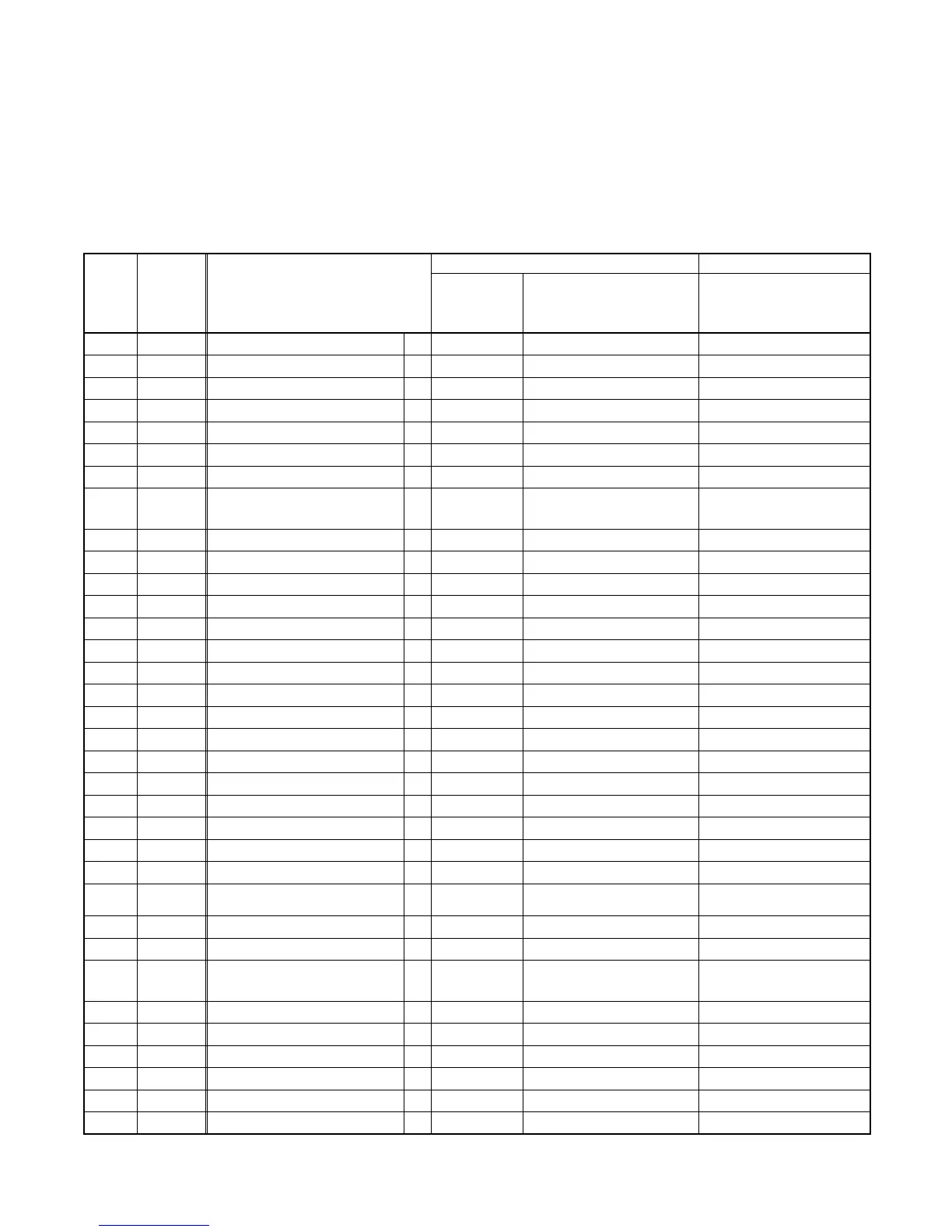
2-4-1 DUALPALDA
DISASSEMBLY/ASSEMBLY PROCEDURES
OF DECK MECHANISM
Before following the procedures described below, be sure to remove the deck assembly from the cabinet. (Refer to
CABINET DISASSEMBLY INSTRUCTIONS on page 1-6-1.)
All the following procedures, including those for adjustment and replacement of parts, should be done in Eject
mode; see the positions of [45] and [46] in Fig.DM1 on page 2-4-3. When reassembling, follow the steps in reverse
order.
STEP
/LOC.
No.
START-
ING
No.
PART
REMOVAL INSTALLATION
Fig. No.
REMOVE/*UNHOOK/
UNLOCK/RELEASE/
UNPLUG/DESOLDER
ADJUSTMENT
CONDITION
[1] [1]
Guide Holder A T DM3 2(S-1)
[2] [1] Cassette Holder Assembly T DM4
[3] [2]
Slider L T DM5 (S-2)
[4] [2]
Slider R T DM5 (S-3)
[5] [4]
Lock Lever T DM5 (S-4),*(P-1)
[6] [2] C Plate T DM5
[7] [7]
Cylinder Assembly T DM1,DM6 Desolder, 3(S-5)
[8] [8]
Loading Motor Assembly T DM1,DM7
Desolder, LDG Belt,
2(S-6)
[9] [9]
AC Head Assembly T DM1,DM7 (S-7)
[10] [2] Tape Guide Assembly T DM1,DM8 *(P-2)
[11] [10]
Door Opener B T DM1,DM8 *(L-1),*(L-2)
[12] [11]
Pinch Arm (B) T DM1,DM8 *(P-3)
[13] [12]
Pinch Arm (A) Assembly T DM1,DM8
[14] [14] FE Head T DM1,DM9 (S-9)
[15] [15]
Prism T DM1,DM9 (S-10)
[16] [2]
Slider Shaft T DM10 (S-11),*(L-3)
[17] [16]
C Drive Lever L T DM10
[18] [16] C Drive Lever R T DM10
[19] [7],[10] Capstan Motor B DM2,DM11 3(S-12), Cap Belt
[20] [20]
Clutch Assembly(HI) B DM2,DM12 (C-1)
[21] [20]
Center Gear B DM12
[22] [22] Cam Holder F B DM2,DM13 (C-2)
[23] [22] Cam Gear (B) B DM2,DM13 (C-3),*(P-4)
[24] [24]
Mode Gear B DM2,DM14 (C-4)
[25]
[20],[23],
[24]
Mode Lever(HI) B DM2,DM14 (C-5), *(L-4)
[26] [22]
Worm Holder B DM2,DM14 (S-15)
[27] [26]
Pulley Assembly B DM2,DM14
[28] [22],[25]
Cam Gear (A) B DM2,DM14
(+)Refer to Alignment
Sec.Pg.2-4-10
[29] [20] TR Gear C B DM2,DM14 (C-6)
[30] [29]
TR Gear Spring B DM14
[31] [30]
TR Gear A/B B DM1,DM14
[32] [31]
FF Arm(HI) B DM1,DM14
[33] [21],[25] Idler Assembly(HI) B DM1,DM15 *(L-5)
[34] [25]
BT Arm B DM2,DM15 *(P-5)