5-2 FL9.1EA
1. Purity Check Mode
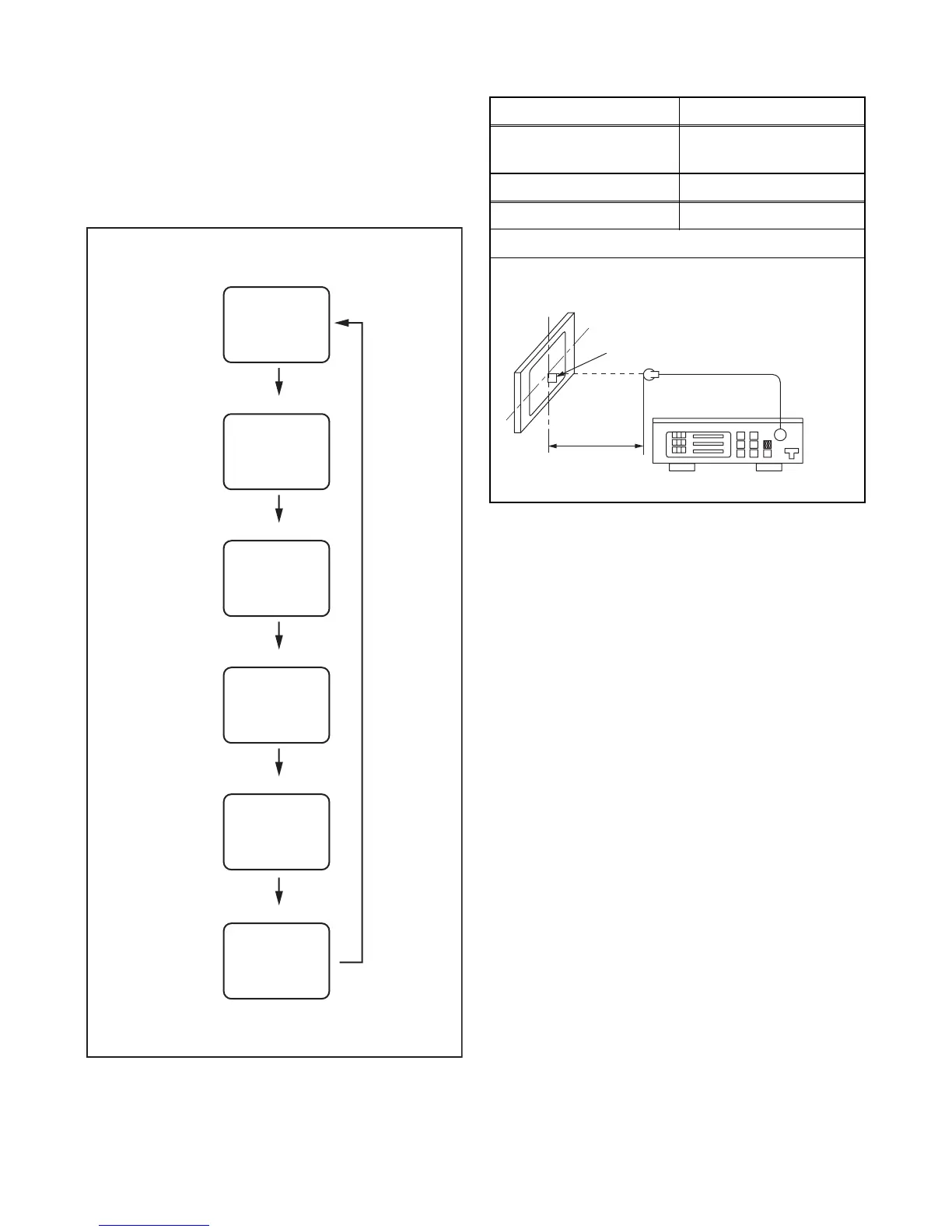
This mode cycles through full-screen displays of red,
green, blue, and white to check for non-active pixels.
1. Enter the Service mode.
2. Each time pressing [7] button on the service
remote control unit, the display changes as
follows.
2. VCOM Adjustment
Note: LC321SSX, 32MF369B/F7: VCOM adjustment
is not required.
1. Operate the unit for more than 20 minutes.
2. Set the color analyzer and bring the optical
receptor to the center on the LCD-Panel surface
after zero point calibration as shown above.
Note: The optical receptor must be set
perpendicularly to the LCD Panel surface.
3. Enter the Service mode.
4. Press [3] button on the service remote control unit.
[LC320SLX (Serial No. : DS1A**********),
LC320SLX (Serial No. : DS2A**********),
LC320SLX (Serial No. : DS4A**********),
32MF339B/F7, LC320SSX, LC320EMXF
LC320EMX (Serial No. : DS1A**********),
LC320EMX (Serial No. : DS2A**********),
LC320EMX (Serial No. : DS4A**********)]
Press [2] button on the service remote control unit.
[LC320EMX (Serial No. : DS3A**********),
LC320SLX (Serial No. : DS3A**********)]
5. Press [CHANNEL UP/DOWN] buttons on the
service remote control unit so that the color
analyzer value becomes minimum.
[7] button
Note:
When entering this mode, the default setting is White mode.
Purity Check Mode
[7] button
Red mode
Green mode
Blue mode
Black mode
[7] button
White mode
[7] button
[7] button
White 20% mode
[7] button
Test Point Adj. Point
Screen
[CHANNEL UP/DOWN ]
buttons
M. EQ. Spec.
Color analyzer See below
Figure
Color Analyzer
To avoid interference from ambinent
light, this adjustment should be
performed in a dark room.
L = 3 cm
Perpendicularity