EasyManua.ls Logo

Furinno 14098R1 User Manual

Furinno 14098R1
2 pages
To Next Page IconTo Next Page
Page #1 background imageLoading...
Page #1 background image
Assembly Instruction
Customer Service
Tel/Fax: 281.500.9372
Toll Free: 773.299.8111 (Mon - Fri 9am - 5pm)
Email: support@furinno.com
WARNING:
>This unit has been designed to support the
maximum loads shown. Exceeding these
load limits could cause sagging, instability,
product collapse, and/or serious injury.
>DO NOT allow children to climb on unit.
>Put heavier items on lower shelves.
its Space. its Budget
www.furinno.com
6.1 Attach Top Panel(A) the the assembled unit and tighten Mini Fix Cam(2).
6.2 Insert Top Cap(8)and slide in Keyboard Panel(G).
STEP 6
Attach Panel(C,E,F)to the assembled unit in Step 4 using Large Screw(4), as shown:
STEP 5
Recommended Maximum Weight
Furinno Computer Desks 14098R1
1409820140818
*Unit in Pound(lbs)
20
10
Tool RequiredTool RequiredNo Tools Required
Recomm. 1 PersonRecomm. 2 Person
Approx. 5 minutesApprox. 10 minutesApprox. 15 minutesApprox. 20 minutesApprox. 30 minutes
Question and Answer IconNeed help?

Do you have a question about the Furinno 14098R1 and is the answer not in the manual?

Furinno 14098R1 Specifications

General IconGeneral
BrandFurinno
Model14098R1
CategoryIndoor Furnishing
LanguageEnglish

Summary

Step 5: Attach Panels

Attach Panel (C, E, F) using Large Screw (4)

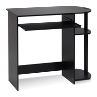
Attach panels C, E, and F to the assembled unit using large screws as shown in the diagram.

Step 6: Attach Top Panel and Keyboard Panel

Attach Top Panel (A) and tighten Mini Fix Cam (2)

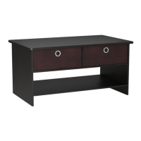
Attach the top panel (A) to the unit and secure it by tightening the mini fix cam.

Insert Top Cap (8) and slide in Keyboard Panel (G)

Insert the top cap (8) and slide the keyboard panel (G) into its designated position.

Recommended Maximum Weight

Weight Limit Warning and Usage Instructions

Exceeding load limits can cause sagging, instability, collapse, or injury. Do not allow children to climb.

Step 1: Install Hardware and Runners

Install Mini Fix Bolt (1) on Panel (A)

Install mini fix bolts (1) onto panel A as indicated in the diagram.

Install Runner A (10) on Panel G with Small Screw (3)

Attach runner A (10) to panel G using small screws (3) following the installation guide.

Step 2: Attach Runners and Fix Cams

Attach Runner B (10) on Panels C, D

Install runner B (10) onto panels C and D using small screws (3).

Insert Mini Fix Cam (2) and Dowel (5)

Insert mini fix cams (2) and dowels (5) into pre-drilled holes on panels C, D, and F, ensuring correct orientation.

Step 3: Attach Shelf Panel with Poles and Legs

Attach Shelf Panel (B) with Pole (6, 7) and Round Leg (9)

Connect shelf panel (B) to the assembly using poles (6, 7) and round legs (9) as illustrated.

Step 4: Attach Right Side Panel

Attach Right Side Panel (D) using Large Screw (4)

Secure the right side panel (D) to the partially assembled unit with large screws (4).

Useful Hints Before You Start

Assembly Guidance and Precautions

Follow instructions carefully, identify parts, assemble on protective surfaces, and use mild cleansers.

Related product manuals