AR-PRO – AC LINE VOLTAGE REGULATOR
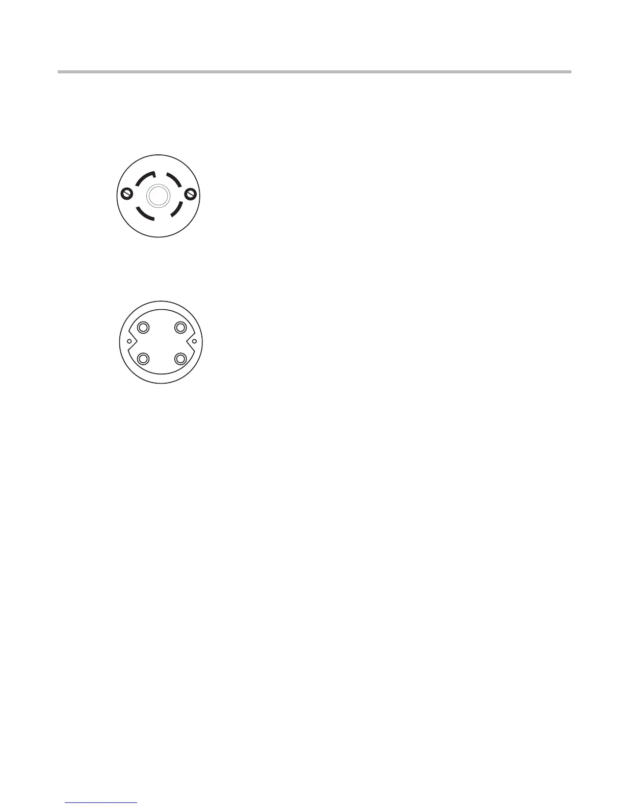
Refer to the following diagrams for wiring the twist-lock
All wiring confi gurations except North America
Wire hot lead to X (black in North America; black,
brown, or black with white stripes in Europe). Wire the
neutral to W (white in North America; blue in Europe).
Wire the equipment ground to G (green in North Amer-
ica; green with yellow stripes in Europe).
Wire the two hot leads to
X and Y (black, and white or red), and the equipment
ground to G (green). Since the USA 220-240 doesn’t
use a neutral, you don’t need to wire it.
because of the lack of a neutral, it is essential that
all equipment powered by an AR-PRO be properly
grounded! Never cut off the power cord ground pin
or use a “cheater” adaptor on any of your equip-
ment. Output neutral will have voltage.
When dealing with high currents such as those handled
by the AR-PRO, the supply cable itself must be con-
sidered part of the load. As such, the length, gauge,
and temperature rating of the insulation must be taken
into account. The minimum wire gauges we suggest
may not be large enough when the cable run is longer
than about 20 feet (7 meters). The smaller the cable
conductors are, the more fl uctuation of input voltage
there will be. This is due to the greater voltage drop.
For example, the recommended minimums will result
in a drop of approximately 1.0 volt for each 30 feet (10
Increasing the cable by one AWG size will reduce the
drop to 1 volt per 45 feet (15 meters). Bigger is defi -
nitely better in this case.
The connector used at the source end should be rated at
least 250V-15A for high range operation, or 120V-30A
for low range operation. If in doubt, consult a licensed
electrician when installing your AR-PRO.
Because its toroidal transformer design has minimal
magnetic leakage, the AR-PRO may be successfully
installed in the same rack as other equipment. Though
small for a device capable of handling 30 amps, this
leakage is not zero. It is wise to avoid positioning the
AR-PRO immediately adjacent to equipment which
handles low-level signals, such as preamps, mike
mixers, etc. Power amps or other high level devices
would make better “rack neighbors.” If excessive hum
or buzz is present in the audio signal, you may be able
to reduce or eliminate it by leaving more empty spaces
Suggested rack locations would be near the top or bot-
tom, with the bottom preferred due to the AR-PRO’s
weight. Because the AR-PRO generates considerable
heat, leaving at least one empty space above and one
below is recommended to aid in convective cooling. As
with any rack-mount equipment, be sure to use 10-
32 machine screws for mounting in the rack’s tapped
holes. In particular, beware of 10-24 screws, which may
fi t, if forced, but will strip the threads. To avoid marring
the front panel fi nish, use plastic washers under the
Adjustable rear rack ears (RPM-2, sold separately)
permit the most secure rack installation. It is essential
to use them when mounting the AR-PRO in any rack
position other than the bottom. If your rack has no
rear rack rails, you may wish to install them or at least
substitute securely mounted blocks of wood.
The rear rack ears can be attached to the wood blocks
with wood screws. They can be adjusted to any rail-
to-rail spacing from 17 to 18.5 inches by loosening the
three adjusting screws on each side, sliding the ears to
a new position, and retightening them.
125/250V
.
30A.
NEMA
L14-30
G
W
X
Y
(EQUIPMENT�
GROUND)
(NEUTRAL)
(HOT LEAD)
(USA 220-240 ONL
Y)�
FRONT VIEW
REAR VIEW
G
W
X
Y
 Loading...