


J
jason59Jul 30, 2025
What to do if nothing appears on the Furuno Marine Radar display or the contrast is poor?
- MmichaelsmithJul 30, 2025
If nothing is showing on the display or the display contrast is poor, try adjusting the brilliance.
What to do if nothing appears on the Furuno Marine Radar display or the contrast is poor?
If nothing is showing on the display or the display contrast is poor, try adjusting the brilliance.
How to fix Furuno 1932 MARK-2 Marine Radar if the control panel does not light?
If the control panel does not light, here are a few things to try: * Adjust the control panel back-lighting on the OTHERS menu. * Check if the battery may have discharged. * Check the fuse in the power cable.
Warning about microwave radiation from the scanner and necessary precautions.
Details RF energy hazards and safe distances from the scanner aperture.
Covers electrical shock hazards, misuse warnings, and importance of qualified personnel.
Statement of compliance with R&TTE Directive and applicable technical standards.
Introduction to the radar manual and a summary of its key features and benefits.
Explains the term RADAR and its basic principles.
Describes how radar calculates distance based on signal travel time and direction.
Describes the Plan Position Indicator (PPI) display and target echo representation.
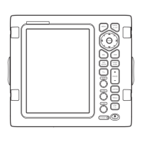
Identifies and describes the functions of various controls on the radar panel.
Details the procedures for powering the radar on, off, and placing it in stand-by mode.
Guides on adjusting GAIN for sensitivity and BRILL for display brightness.
Describes the use of A/C SEA and A/C RAIN controls to minimize unwanted echoes from weather.
Explains methods for measuring target range and bearing using rings, cursors, and VRMs/EBLs.
Details how to measure target bearing using the Electronic Bearing Line (EBL) and cursor.
Explains how to use the Offset EBL for predicting collision course and measuring between targets.
How to off-center the display to view the surrounding situation without changing range.
How to zoom in on specific areas of the radar display for a closer look.
Guides on navigating and selecting items within the radar's menu system.
Explains how to choose between Head-up, Course-up, North-up, and True motion display modes.
How to use echo stretch to magnify long-range echoes and echo trail for collision avoidance.
Details methods to suppress interference from other radar sources.
Setting up guard zones for audible alarms when targets enter or exit the designated area.
Explains the Watchman function for periodic radar transmission to check guard zones.
How to display navigation information received via IEC 61162 format on the screen.
Provides a summary of less common functions available in the "OTHER MENU".
Explains function keys, noise rejection, and marker brilliance adjustments.
Explains the cause and reduction of multiple and side-lobe echoes appearing on the display.
Identifies indirect echoes and explains how obstructions create blind or shadow sectors.
Details how to detect and interpret signals from a Search and Rescue Transponder (SART).
Outlines regular maintenance tasks and instructions for safe fuse replacement.
Provides step-by-step guidance to diagnose and resolve common operational problems with the radar.
How to perform self-tests and information on the expected life expectancy of the magnetron.
Overview of the Auto Plotter ARP-10, its capabilities, specifications, and menu navigation.
Guides on how to turn the Auto Plotter's tracking and display features on and off.
Procedures for manually and automatically acquiring and tracking radar targets with the ARP-10.
How to display calculated target data (range, bearing, speed) and motion vectors.
Setting up past position trails and understanding CPA/TCPA and lost target alarms.
Guides on configuring CPA and TCPA alarm limits for collision risk detection.
Details general performance parameters like display system, range, resolution, and accuracy.
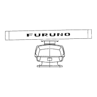
Technical details of the scanner unit, including radiator, beamwidth, and rotation speed.
Technical details of the transceiver module and display unit, including frequency, power, and interface.
Specifies operating limits, power needs, physical dimensions, and compass safe distances.
| Brand | Furuno |
|---|---|
| Model | 1932 MARK-2 |
| Category | Marine Radar |
| Language | English |