M
Michael VanceSep 9, 2025
What to do if Furuno 1835 data and marks not displayed in transmit?
- TtamaramurraySep 9, 2025
If data and marks are not displayed in transmit, replace the SPU board.
What to do if Furuno 1835 data and marks not displayed in transmit?
If data and marks are not displayed in transmit, replace the SPU board.
Why is my Furuno 1835 Marine Radar power not turning on?
If your Furuno Marine Radar is not powering on, check the following: a blown fuse, the power connector to ensure it's fastened, the power cable connector for corrosion, the power cable for damage, and the battery for correct voltage output.
What to do if Furuno 1835 Marine Radar range is changed but radar picture does not change?
If you change the range on your Furuno Marine Radar and the picture doesn't change, try operating the RANGE key again. If that doesn't work and you cannot operate the RANGE key, replace the keypad. Alternatively, the SPU board may need replacing, or try turning the radar off and on.
How to fix antenna not rotating on Furuno Marine Radar?
If the antenna is not rotating on your Furuno Marine Radar, replace the antenna drive mechanism.
What to check if Furuno 1835 set GAIN to maximum with A/C SEA set at minimum shows marks and indications appear but no noise or echo?
If you set GAIN to maximum with A/C SEA set at minimum, and marks and indications appear but no noise or echo: 1. Check continuity and isolation of coaxial cable. 2. Replace IF amplifier. 3. Check coax line for fasten connection. If connection is good, replace SPU board.
What to do if target is not tracked correctly because of sea clutter on Furuno Marine Radar?
If targets are not tracked correctly on your Furuno Marine Radar due to sea clutter, adjust the A/C SEA and A/C RAIN controls.
What to do if my Furuno 1835 Marine Radar range is changed, but the radar picture does not change?
If the range is changed but the radar picture does not change, try hitting the RANGE key again, or turn the display unit off and on.
What to do if Furuno 1835 Marine Radar range changed but radar picture does not change?
If the range is changed, but the radar picture does not change it may be that the RANGE key has faults, the SPU board needs replacing or there is a video freeze-up. Try to operate the RANGE key. If you cannot operate the RANGE key, replace the keypad. You can also replace the SPU board or turn off and on the radar.
What to do if tuning is correctly adjusted, but sensitivity is poor on Furuno Marine Radar?
If tuning is correctly adjusted but sensitivity is poor on your Furuno Marine Radar, replace the magnetron and contact your dealer.
What to do if Furuno Marine Radar has no response when a key is pressed?
If your Furuno Marine Radar is not responding when a key is pressed, turn the power off and on. If you still do not get a response, the key may be damaged.
General notices and guidelines for using the manual, including grammar and copyright.
Instructions for discarding the product and used batteries according to environmental regulations.
Warning about RF radiation from the radar antenna and safe operating distances.
Hazards related to electrical shock, water ingress, and proper operation procedures.
Information on warning labels attached to the equipment and their importance.
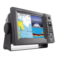
Overview of key features and model specifications for the marine radar series.
Comparison of functions across different radar types (River, Sea, IEC, Russian-River).
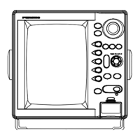
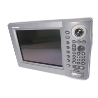
Description of the display unit's keys, controls, and their functions.
Procedure for powering the radar on, off, and initiating transmission.
Explanation of various indicators and symbols displayed on the radar screen.
Steps to adjust the brightness of the display and panel controls.
Guide to navigating the radar's menu system and understanding menu items.
Procedures for automatic and manual tuning of the radar receiver for optimal reception.
Explanation of different display modes like Head Up, Course Up, North Up, and True Motion.
Step-by-step guide to choose and set the desired radar display mode.
Detailed explanation of the characteristics of each radar display mode.
How to adjust the radar's range scale for optimal target viewing.
Method for adjusting the radar receiver's sensitivity automatically or manually.
Techniques for minimizing unwanted echoes from sea reflections using A/C SEA control.
Methods for reducing unwanted echoes caused by rain or snow using A/C RAIN control.
Using the A/C Auto feature to automatically adjust sea and rain clutter.
Functionality of the cursor for finding target range, bearing, and position data.
How to use the interference rejector to minimize signal interference from other radars.
Methods for measuring target range using fixed rings, VRM, or cursor.
How to adjust the brightness of the radar range rings for better visibility.
Using the Variable Range Marker (VRM) to accurately measure target distances.
Using the Electronic Bearing Line (EBL) to measure the bearing to a target.
Procedure to measure the distance and bearing between two selected targets.
How to change the pulselength setting for optimal range detection or resolution.
Configuring target alarms to alert when targets enter or exit a defined zone.
Steps to define the area for target alarm activation.
How to shift the ship's position on the display for expanded view.
Using the zoom feature to magnify specific areas or targets on the radar display.
Adjusting echo stretch for target visibility and echo average for target identification.
Displaying simulated afterglow of targets to track their movement.
Configuring trail duration, mode (True/Relative), and gradation.
Using the TLL key to send target data to a chart plotter or mark its position.
Adjusting the brilliance of echoes, rings, marks, and characters.
Creating and applying custom radar settings for different navigation conditions.
Step-by-step guide to configure and save custom setup profiles.
Customizing function keys (F1, F2, F3) for quick access to desired features.
Using noise rejector and wiper features to improve picture clarity.
Method to eliminate false echoes caused by targets at twice the normal range.
Activating the Watchman function for periodic radar checks and alerts.
Setting preset and custom color schemes for optimal viewing in different light conditions.
Showing and configuring navigation data on the standby screen and data box.
Adjusting dynamic range to enhance target visibility by reducing weak echoes.
Modifying echo characteristics curves to improve target detection.
Displaying waypoint markers and viewing active alarm messages.
Choosing between Normal and Full Screen display for echoes.
Customizing radar settings via the Initial sub menu within the System menu.
Selecting units of measurement for various radar parameters.
Defining sectors to blank specific areas for safety or to avoid mast echoes.
Configuration options for view position, menu transparency, and echo color modes.
Using the radar as a remote display for another unit.
Basic properties of radar, including minimum and maximum ranges.
Explanation of bearing and range resolution and their importance in radar performance.
Accuracy of bearing and range measurements and factors affecting them.
Identification and causes of false echoes like multiple, sidelobe, virtual, and shadow sectors.
Understanding and reducing multiple echoes caused by strong targets.
Identifying and reducing false echoes caused by radar sidelobes.
Recognizing and understanding virtual images as false echoes.
Explaining shadow sectors where targets cannot be detected due to obstructions.
How the radar detects and displays signals from a SART device.
Details on SART signals and how they appear on the radar display.
How RACON signals are displayed on the radar screen.
Important safety and operational precautions specific to ARPA usage.
Explanation of controls and basic operations for using the ARPA system.
How to enable or disable the ARPA display on the radar screen.
Procedures for manually or automatically acquiring and tracking targets with ARPA.
Steps for manually selecting and acquiring targets for ARPA tracking.
Configuring and enabling automatic acquisition of targets within a defined area.
Methods to cancel tracking for selected or all ARPA targets.
Procedure to stop tracking a specific ARPA target.
How to cancel tracking for all acquired ARPA targets simultaneously.
Understanding and configuring target vectors (speed, course, time, reference).
Adjusting vector display time and reference (Relative/True).
Displaying the vector representing your ship's movement.
Showing past positions of tracked ARPA targets to analyze movement.
Displaying detailed data for selected ARPA targets in the data box.
Setting alarms for Closest Point of Approach (CPA) and Time to CPA (TCPA).
Configuring proximity alarms for ARPA targets based on distance.
Managing and clearing lost ARPA targets from the display.
Changing the color of ARPA target symbols for better visibility.
Overview of controls for interacting with AIS data.
How to enable or disable the display of AIS targets.
Understanding the different symbols used to represent AIS targets.
Managing AIS targets by activating or sleeping them for display clarity.
Showing detailed data for selected AIS targets.
Options for sorting AIS targets by range, sector, CPA, or TCPA.
Limiting the display to show AIS targets within a specific range.
Filtering AIS targets to display only those within a defined sector.
Limiting the number of AIS targets shown on screen to reduce clutter.
Configuring vectors for AIS targets to show course and speed.
Displaying past positions of tracked AIS targets.
Setting collision alarms (CPA/TCPA) for AIS targets.
Configuring proximity alarms for AIS targets based on distance.
Managing and clearing lost AIS targets from the display.
Changing the color of AIS target symbols.
Preventing alarms for AIS targets moving below a set speed threshold.
Selecting GPS or WAAS modes for navigation.
Choosing the correct geodetic datum for accurate navigation.
Configuring the WAAS system for enhanced positioning accuracy.
Monitoring the status and signal strength of GPS and WAAS satellites.
Performing a cold start to reinitialize the GPS receiver when needed.
Regular checks and maintenance tasks to ensure equipment longevity.
Procedure for replacing fuses and important safety warnings.
Information on the expected lifespan of key components like magnetron and LCD backlight.
Common problems and solutions for restoring normal operation.
Troubleshooting steps for hardware and software issues, typically for qualified personnel.
Performing self-tests to check system operation and identify potential issues.
Running a test to verify the functionality and display patterns of the LCD screen.
Performing diagnostic tests for the ARPA and GPS systems.
Settings related to display brilliance, color palettes, and character appearance.
Configuration settings for display modes, zoom, off-center, and data box.
Settings for adjusting echo sensitivity, clutter, stretch, and average.
Options for configuring and managing custom radar settings.
Settings for target alarms, Watchman, panel/external buzzers, and alarm status.
Configuration of target trails, including time, gradation, color, mode, and restart.
Settings for radar tuning modes and initial tuning adjustments.
Various settings including function keys, EBL reference, VRM unit, and cursor position.
Settings specific to ARPA operation, such as display, color, acquisition, and lost targets.
Settings related to AIS display, color, sorting, range, sector, and alarms.
GPS and WAAS related settings, including mode, datum, satellite monitor, and self-test.
System-level configurations like key beep, offcenter speed, compass type, NMEA ports, and units.
Detailed specifications including range scales, pulselength, resolution, and accuracy.
Technical details of the antenna unit, such as radiator type, length, beamwidth, and sidelobe levels.
Specifications for the transceiver module, including radiation type, frequency, and output power.
Details about the display unit, screen type, effective diameter, and range scales.
Information on heading signals, NMEA interfaces, USB, and input/output data sentences.
Power consumption details for different radar models and rectifier options.
Operating temperature, humidity, protection ratings, and vibration standards.
Information on coating colors and safe distances for compasses.
| Display Size | 10.4 inches |
|---|---|
| Power Output | 4 kW |
| Display Type | Color LCD |
| Transmitter Power Output | 4 kW |
| Resolution | 640 x 480 pixels |
| Antenna Type | Radome |
| Frequency | 9410 MHz ±30 MHz |
| Range Scales | 0.25, 0.5, 0.75, 1.5, 3, 6, 12, 24, 48 nautical miles |
| IP Rating | IPX6 |
| Antenna Length | 6 feet |