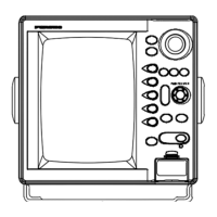
10.4 Multi-Color LCD RADAR
10.4 Multi-Color LCD RADAR
SPECIFICATIONS OF MODEL 1835/1935/1945
ANTENNA RADIATOR
Type
MODEL1835 Printedarray
MODEL1935/1945 Slottedwaveguidearray
Length and Rotation Speed
MODEL1835 Radome60cm(RSB-0071)24RPM
MODEL1935 Open100cm(XN10A)24or48RPM
MODEL1945 Open120cm(XN12A)24or48RPM
Wind Load (for MODEL 1935/1945)
24RPM 100knrelativewind
48RPM 70knrelativewind
Beamwidth
ANT9210: Hor.4.0°,Vert.20°
XN10A: Hor.2.4°,Vert.22°
XN12A: Hor.1.9°,Vert.22°
RF TRANSCEIVER
Frequency
9410±30MHz(X-band)
Output Power
MODEL1835/1935 4kW
MODEL1945 6kW
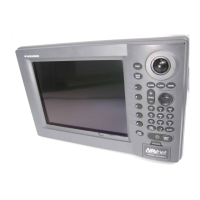
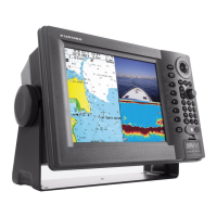
DISPLAY
Screen Size
10.4"colorLCD
Pixel Number
640(H)x480(V),VGA
Effective Diameter
158mm
Echo Colors
32levels
Display Modes
Head-up,Course-up*,North-up*,
Trueview*,Truemotion**
*Headingdatarequired
**Headingandpositiondatarequired
Range Units
nm,sm,km
Range Scales and Range Ring Intervals (nm)
Range: 1/16,1/8,1/4,1/2,3/4,1,1.5,1.6,2,3,
3.2,4,6,8,12,16,24,32,36,48*,64**
Rings: 1/32,1/16,1/8,1/4,1/2,0.8,1,2,3,4,
6,8,12*,16**
*ForMODEL1935/1945
**ForMODEL1945
Minimum Range
25m
Range Discrimination
25m
Echo Trails
Type Trueorrelativetrails
TrailLength: 15,30sec.,1,3,6,15,30min.,
orcontinuousTrail
TrailWidth: Narrow,Normal
Target Tracking (Required optional board ARP-11)
Acquisition:Auto,Manual
Numberoftargets:10targetsmax
AIS Functions (Data input from AIS is required)
Symbols:Sleeping,Activated,Dangerous,Selected,Losttargets
Numberoftargets:100targetsmax.
INTERFACE
Input
AD-10orIEC61162NMEA0183Ver.1.5/2.0/3.0
Output
IEC61162NMEA0183Ver.1.5/2.0/3.0
ENVIRONMENT
Temperature
AntennaUnit: -25°Cto+55°C(-13°Fto+131°F)
DisplayUnit: -15°Cto+55°C(5°Fto+131°F)
Waterproofing
AntennaUnit: IEC60529IP26
DisplayUnit: IEC60529IP55
POWER SUPPLY
MODEL1835 12-24VDC:4.1-2.0A
MODEL1935 12-24VDC:6.8-3.3Afor24rpm
8.2-3.8Afor48rpm
MODEL1945 12-24VDC:7.3-3.5Afor24rpm
8.8-4.1Afor48rpm
EQUIPMENT LIST
Standard
1.DisplayUnit 1unit
2.AntennaUnit(Specifywhenordering) 1unit
3.AntennaCable
MODEL1835 10,15,20or30m1pc
MODEL1935/1945 10,15,20or30m1pc
4.PowerCable5m1pc.
5.Installationmaterialsandspareparts 1set
Option
1.AutoPlotterARP-11
2.Rectifier
MODEL1835 PR-62
MODEL1935/1945 RU-3423
3.
ExternalAlarmBuzzer
OP03-21
4.InterfaceCable
MJ-B24LPF0010 10,20,or30m
MJ-A7SPF0007-050C 5m
MJ-A6SPF0007-100C 10m
MJ-A10SPFW0001+R 0.2m
5.AntennaBracket(forMODEL1835) OP03-92
12033SK Printed in Japan
Catalogue No. R-196b
www.furuno.com
COLOR LCD SOUNDER 10.4 Multi-Color LCD RADAR
All brand and product names are registered trademarks, trademarks
or service marks of their respective holders.
SPECIFICATIONS SUBJECT TO CHANGE WITHOUT NOTICE
1835/1935/1945
Model
1835/1935/1945
Model
1835/1935/1945
ModelModel
AUTO
Auto Tuning
(Sensitivity)
Enhanced
Sunlight Viewable
Enhanced
Sunlight Viewable
Bonded LCD
Bonded
LCD
AIS
AIS
Target Tracking
Target
Tracking
MODEL 1835 and FCV-295 Helm Solution
The cosmetic design of the 1835/1935/1945 Radar series matches with that of the FCV-295 digital echo sounder with
10.4" bonded LCD. Installed side-by-side, they will enhance the look of your helm.
285 11.2"
310 12.2"
323 12.7"
308 12.1"
169
6.7"
129 5.1"
17
0.7"
22 0.9"
35°
25
1.0"
62 2.4"
BOW
Cable entry
278 10.9"
602 23.7"
348 13.7"
266
10.5"
Cable entry
(160 6.3")
(160 6.3")
Fixing holes
4-M10
640
25.2"
BOW
445 17.5"
357 14.1"
542 21.3"
250 9.8"
213 8.4
"
438 17.2"
340 13.4"
250 9.8"
XN10A :1036 40.8"
XN12A :1255 49.4"
4- 15
Fixing holes
200 7.9"
200 7.9"
25
100/110/115/
220/230VAC
12-24 VDC
MJ-B24LPF0002
10/15/20/30 m
MJ-B24LPF0005
10/15/20/30 m
MJ-A10SPFW
0001+R
MJ-A7SPF
0007-050C
MJ-B24
LPF-0010
MJ-A7SPF0007-050C
MJ-A7SPF0007-050C
MJ-A6SPF0007-100C
Display Unit
RDP-152
5.4kg11.9lb
Antenna Unit
RSB-0071
8kg17.6lb
Antenna Unit
XN10A:22kg48.5lb
XN12A:25kg55.1lb
Display Unit
ARP-11
GPS Navigator, AIS
Sounding Equipment
Satellite Compass
SC-30*/50/110
Heading Sensor
PG-500
*For further info, contact our depot
Option or local supply
Gyro Converter AD-100
Rectifier
GPS Navigator, AIS
Sounding Equipment
Gyrocompass
External Alarm Buzzer
for MODEL 1835
Remote Display*
INTERCONNECTION DIAGRAM
Antenna Unit
for MODEL 1935/1945