J
John NelsonAug 28, 2025
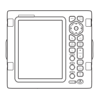
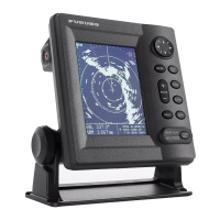
How to fix Furuno Marine Radar true motion presentation not working correctly?
- JJoseph RosarioAug 28, 2025
If the true motion presentation on your Furuno Marine Radar is not working correctly, check that the setting of [Display Mode] in the [Display] menu is set to [True Motion]. Also, verify that the heading and position data are input and correct.