Do you have a question about the Furuno CH-26 and is the answer not in the manual?
Defines DANGER notices for severe injury or death if hazards are not avoided.
Defines WARNING notices for severe injury or death if hazards are not avoided.
Defines CAUTION notices for minor injury or property damage if hazards are not avoided.
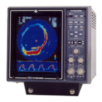
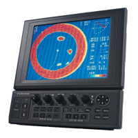
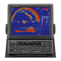
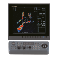
Details the 10/14-inch color CRT display system and its capabilities.
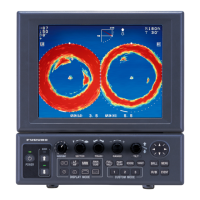
Describes the 8 colors used for signal strength indication.
Explains the three available display modes: PPI, expanded PPI, and echo sounder.
Lists operating frequency, beamwidth, and output power of the transceiver.
Itemizes all components included in the system with weights and quantities.
Lists optional accessories available for CH-24 and CH-26 models.
Instructions for installing the display unit in a suitable location.
Guidelines for mounting the transceiver unit on a bulkhead or hull unit.
Procedures and considerations for installing the hull unit.
How to install the optional motion sensor for ship's motion measurement.
Guidelines for installing the optional rectifier unit for power conversion.
Information regarding the transducer cable length and handling.
General procedure for connecting wires to terminal boards.
Diagram showing unit connections and cabling layout.
How to synchronize transmissions between multiple sonars.
Initial checks performed on dry dock or slipway.
Comprehensive checks performed before system operation.
Procedure to align the unit's heading with the ship's heading.
How to perform system self-checks and interpret results.
Adjusting unit settings via internal DIP switches for user requirements.
Modifying the transducer travel range from 400mm to 250mm.
Calibrating the motion sensor to compensate for ship's inclination.
Instructions for connecting an optional monitor TV using the VDO board.
| Type | Searchlight Sonar |
|---|---|
| Frequency | 60 kHz |
| Operating Depth | Up to 1000 meters |
| Display Modes | A-Scope |
| Beam Width | 12 degrees |