EasyManua.ls Logo

Furuno CH-270 User Manual

Furuno CH-270
118 pages
To Next Page IconTo Next Page
Page #1 background imageLoading...
Page #1 background image
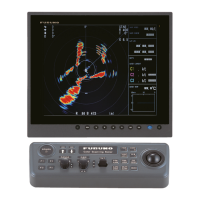
COLOR LCD
SEARCHLIGHT SONAR
CH-270
OPERATOR'S MANUAL
www.furuno.co.jp
MODEL
Back

Table of Contents

Other manuals for Furuno CH-270

Questions and Answers:

Furuno CH-270 Specifications

General IconGeneral
BrandFuruno
ModelCH-270
CategorySonar
LanguageEnglish

Summary

1. OPERATIONAL OVERVIEW

1.1 Control Description

Explains the functions of each button and control on the main unit.

1.2 Remote Controller

Details the functions and controls of the optional remote controller.

1.3 Turning the Power On/Off

Step-by-step instructions for powering the equipment on and off.

1.4 Raising, Lowering the Transducer

Procedures for safely raising and lowering the transducer.

1.5 Choosing a Display

Describes the eight available display modes and how to select them.

1.6 Adjusting Screen Brilliance, Panel Dimmer

How to adjust screen brightness and panel backlighting levels.

1.7 Adjusting the Gain

Guidance on adjusting the receiver sensitivity for optimal echo display.

1.8 Basic Menu Operation

How to navigate and operate the system's menu structure.

2. HORIZONTAL MODE

2.1 Operational Overview

Overview of the typical operating sequence for horizontal mode.

2.2 Typical Horizontal Mode Display

Explanation of the elements and indicators on the horizontal display.

2.3 Choosing the Range

How to select the detection range based on target or depth.

2.4 Choosing Sector Width

How to adjust the width of the transducer's training sector.

2.5 Choosing Train Center

Setting the center bearing for the sonar's training sector.

2.6 Choosing the Tilt Angle

How to set the transducer's vertical tilt angle for optimal detection.

2.7 Choosing the Training Speed

How to select the speed at which the transducer scans the sector.

2.8 Finding Echo Position with the Cursor

Using the cursor to measure range, depth, and bearing to targets.

2.9 Event Marker

How to mark and manage important locations on the sonar display.

2.10 Depth and Horizontal Range Markers

Measuring depth and range to targets using specific markers.

2.11 Adjusting the Picture

Techniques for improving picture clarity by suppressing noise and reflections.

2.12 Target Lock

How to automatically track specific targets like fish schools or positions.

2.13 Horizontal Menu Overview

Description of the various options available in the HORZ menu.

2.14 Interpreting the Horizontal Display

Understanding how the sonar picture is formed and interpreting echo displays.

3. VERTICAL SCAN MODE

3.1 Operational Overview

Overview of the typical operating sequence for vertical scan mode.

3.2 Displaying Vertical Scan Mode Display

Explanation of the elements and indicators on the vertical scan display.

3.3 Choosing the Range

How to select the detection range for vertical scan mode.

3.4 Choosing Train Center

Setting the center bearing for the vertical scan beam.

3.5 Choosing Display Sector

How to adjust the width of the transducer's training sector in vertical scan.

3.6 Choosing Sector Center

Setting the center direction of the sounding beam in the vertical direction.

3.7 Choosing the Tilt Speed

How to select the scanning speed for the transducer in vertical scan.

3.8 Finding Echo Position with the Cursor

Using the cursor to measure range and depth in vertical scan mode.

3.9 Event Marker

How to mark and manage important locations on the vertical scan display.

3.10 Depth and Horizontal Range Markers

Measuring depth and range in vertical scan mode using markers.

3.11 Adjusting the Picture

Techniques for improving picture clarity in vertical scan mode.

3.12 Interpreting the Vertical Scan Display

Understanding and interpreting the vertical scan display and sample echoes.

4. ECHO SOUNDER MODE

4.1 Operational Overview

Overview of the typical operating sequence for echo sounder mode.

4.2 Typical Echo Sounder Display

Explanation of the elements and indicators on the echo sounder display.

4.3 Choosing the Range

How to select the detection range for echo sounder mode.

4.4 Train Direction

Setting the direction of the sounding beam in echo sounder mode.

4.5 Choosing Tilt Angle

How to set the transducer's tilt angle for echo sounder operation.

4.6 Choosing Picture Advance Speed

How to adjust the speed at which new scan lines appear on the screen.

4.7 Measuring Range by Cursor

Using the cursor to measure range to targets in echo sounder mode.

4.8 Event Marker

How to mark and manage important locations on the echo sounder display.

4.9 Range Marker

Using the range marker to measure distance to targets in echo sounder mode.

4.10 Adjusting the Picture

Techniques for improving picture clarity and echo detection in echo sounder mode.

5. MENU OPERATION

5.1 COM1 Menu

Description of settings and functions within the COM1 menu.

5.2 COM2 Menu

Description of settings and functions within the COM2 menu.

5.3 Short-cut Menu, Preset Menu

How to program and use custom mode keys for shortcuts and presets.

5.4 SYSTEM Menu

Overview of the system settings menu and its categories.

5.4.1 Displaying the SYSTEM menu

Steps to access and navigate the main system menu.

5.4.2 SYSTEM SETTING 1 menu description

Details of parameters configurable in System Setting 1.

5.4.3 SYSTEM SETTING 2 menu description

Details of parameters configurable in System Setting 2.

5.4.4 Sonar (horizontal) mode range settings

How to preset the detection ranges for horizontal mode.

5.4.5 Vertical scan mode range settings

How to preset the detection ranges for vertical scan mode.

5.4.6 Echo sounder mode range settings

How to preset the detection ranges for echo sounder mode.

5.4.7 Track range settings

How to set the scale range for the video plotter track display.

5.4.8 Color palette

How to customize echo, background, text, and menu colors.

5.4.9 Language

How to select the menu language for the system interface.

5.4.10 System backup

How to save current system settings to internal memory.

5.4.11 Loading backup data

How to load previously saved system settings.

5.4.12 Transducer frequency adjustment

How to adjust transducer frequency to reduce interference.

5.4.13 Demonstration mode

How to activate a simulated sonar picture for familiarization.

5.4.14 Restoring all default settings

How to reset all system menu settings to their default values.

6. MAINTENANCE, TROUBLESHOOTING

6.1 Preventive Maintenance

Recommended monthly checks for maintaining equipment health.

6.2 Cleaning the Equipment

Instructions for safely cleaning the equipment, including the LCD.

6.3 Hull Unit Maintenance

Maintenance procedures for the hull unit, including lubrication.

6.4 Transducer Maintenance

How to clean and maintain the transducer, especially when dry-docked.

6.5 Fuse Replacement

Guidance on replacing fuses to protect equipment from electrical issues.

6.6 Troubleshooting

Common symptoms of equipment troubles and their remedies.

6.7 Error Messages

List of potential error messages and their meanings or solutions.

6.8 Diagnostics

How to run diagnostic tests to check equipment operation and results.

6.9 Test Pattern

How to display test patterns to check for proper display of colors.

SPECIFICATIONS

1. GENERAL

General technical specifications of the display system and sonar.

1.1 Display System

Details about the display system hardware.

1.2 Transmit Frequency

The operating frequency of the sonar transducer.

1.3 Output Power

The sonar's transmitter output power.

1.4 Range (factory settings)

Default factory settings for detection ranges in different modes.

1.5 Output Pulse Length

The output pulse length characteristics.

1.6 TVG

Technical details regarding the Time Varied Gain (TVG) function.

2. DISPLAY UNIT/ CONTROL UNIT

Specifications related to the display and control unit components.

2.1 Picture Color

Color options for displaying echoes and background.

2.2 Display Mode

List of available display modes for the sonar.

2.3 Combination Display

Types of combined displays supported by the unit.

2.4 External Data Indication

Types of external data that can be displayed.

2.5 Audio Monitor

Specifications for the audio output and speaker.

2.6 Event Mark

Details on the number of event markers supported.

2.7 Target Lock (three functions, selected on menu)

Functions and methods for target lock operation.

3. HULL UNIT

Specifications related to the hull unit and transducer assembly.

3.1 Transducer Travel

The travel distance of the transducer.

3.2 Raise/lower Time

Time taken to raise or lower the transducer.

3.3 Allowable Ship’s Speed

Maximum ship speed allowed during transducer operation.

3.4 Stabilizer

Requirements for the stabilizer function.

3.5 Horizontal Mode Control

Control parameters specific to horizontal mode operation.

3.6 Vertical Scan Mode Control

Control parameters specific to vertical scan mode operation.

4. I/O INTERFACE

Specifications for input/output data formats and standards.

4.1 Data Format

Supported data formats like NMEA 0183.

4.2 Input

List of supported input data types.

4.3 Output

Supported output data types.

5. POWER SUPPLY

Power requirements for different units of the sonar system.

5.1 Transceiver Unit

Power supply specifications for the transceiver unit.

5.2 Hull Unit

Power supply specifications for the hull unit.

5.3 Rectifier

Specifications for the power rectifier.

6. ENVIRONMENTAL CONDITIONS

Operating environmental limits for the equipment.

6.1 Ambient Temperature

Operating temperature range for different units.

6.2 Relative Humidity

Allowed relative humidity levels.

6.3 Waterproofing

Waterproofing ratings (IP codes) for different units.

7. COATING COLOR

Color specifications for the display and transceiver units.

Related product manuals