Do you have a question about the Furuno DS-80 and is the answer not in the manual?
General safety instructions and cautions for operation and handling.
Details about warning labels attached to equipment and their purpose.
Log of changes made to the operator's manual over time.
Covers speed range, distance, depth, frequency, and accuracy.
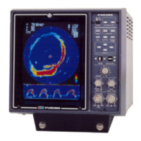
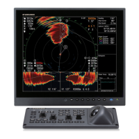
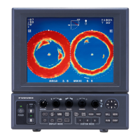
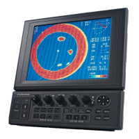
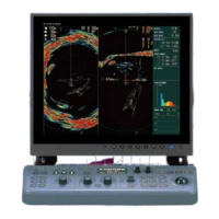
Details on display type, character size, and indications.
Specifies serial and analog signal outputs and inputs.
Details power requirements, ambient temperature, humidity, and vibration.
Specifies unit colors and compass safe distance requirements.
Precautions regarding radiation and compliance with marine equipment directives.
Highlights key features, operation, and compliance with international standards.
Illustrates the connection between various units of the DS-80 system.
Explains how the Doppler Effect is used to measure ship's speed.
Discusses conditions affecting accuracy and proper usage guidelines.
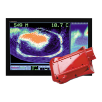
Provides instructions for transducer placement and protection during dry docking.
Identifies and describes the function of each button on the display unit.
Details procedures for turning the equipment on and off.
Instructions for adjusting screen contrast and panel illumination.
How to switch between speed-only and speed-and-distance displays.
Guide to accessing and navigating the main menu options.
Procedures for adjusting and selecting display methods for distance run data.
How to adjust and reset the distance run indication to zero.
Configuration parameters for system setup, including averaging, offsets, and tracking depth.
Information on transducer orientation deviation, not user-adjustable.
How to select between Doppler and GPS speed sources.
Accessing diagnostic tests, dimmer control, and language settings.
Activating and using the demonstration mode for output signal testing.
Instructions for operating optional digital and distance indicators.
How to select display modes on optional indicators.
Adjusting display settings for optional indicators.
Guidelines for preventive maintenance, cleaning, and checks.
How to clean the transducer face to maintain sensitivity.
Information on fuse types and replacement procedures for system protection.
Identifies common issues and their probable causes and remedies.
Steps for running built-in diagnostic tests and checking program IDs.
Explains input/output sentences (GGA, VTG) and data transmission parameters.
Circuit diagram for the IEC61162 receiver port, including load requirements.
Circuit diagram for the IEC61162 transmitter port 1, detailing output capabilities.
Circuit diagram for the IEC61162 transmitter port 2, detailing output capabilities.
Detailed description of the GGA sentence structure and its data fields.
Detailed description of the VTG sentence structure and its data fields.
Detailed descriptions of VBW and VLW sentence structures and their data fields.
Visual identification of components on the DS-800 display unit ICP board.
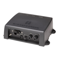
Visual identification of components within the DS-801 distribution box.
Visual identification of components within the DS-810 transceiver unit.
Notes that component-level parts are not listed; major modules are shown in location photos.
Lists printed circuit boards and cables for the display unit.
Lists electrical parts for the transceiver unit, including boards and filters.
Lists electrical parts for the distributor unit, including boards and power supplies.
A form to record calibration data for the DS-80 Doppler Speed Log.
Visual representation of the DS-80's menu hierarchy and settings.
Official declaration of compliance with marine equipment standards and directives.