Do you have a question about the Furuno DS-8500 and is the answer not in the manual?
Describes the meaning and use of safety warning and caution symbols.
Provides essential safety advice for equipment installation.
Specifies safe distances to prevent magnetic compass interference.
Illustrates the overall system setup and component connections.
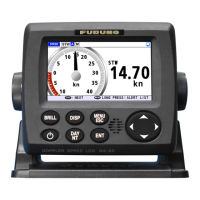
Lists components for the DS-8500 unit.
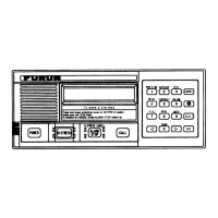
Lists components for the DS-8510 unit.
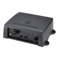
Lists components for the DS-8520 unit.
Lists components for the DS-8530 unit.
Guidelines and procedures for installing the display unit in various configurations.
Considerations and steps for mounting the distributor unit.
Factors for locating and installing the transceiver unit.
General considerations and specific installation methods for transducers.
Installation guidelines for the junction box option unit.
Guidelines for cable routing, noise reduction, and grounding.
Procedures for connecting and waterproofing display unit cables.
Steps for fabricating and connecting distributor unit cables.
Methods for fabricating and connecting transceiver unit signal and transducer cables.
Procedures for connecting junction box cables and ensuring watertightness.
Initial setup for transducers, display units, and language selection.
Navigating and understanding the main equipment menu options.
Adjusting transducer parameters, offset, and ship trim.
Configuring I/O ports, channels, LAN, and communication settings.
Using monitors and diagnostic tools for system status and troubleshooting.
Performing speed trials, system resets, and basic calibration.
Adjusting offset values for analog output ports.
Explains the structure and meaning of JIS cable nomenclature.
Lists measurements of commonly used JIS cables with Furuno products.
Defines NMEA sentence priorities, data transmission format, and digit settings.
Details common NMEA sentences used by the system.
Outlines the process for calibrating speed using ship speed trials.
Explains methods for calculating speed and using survey poles for calibration.
Provides a template for recording calibration test data and results.
Lists components for the DS-8500 unit.
Lists components for the DS-8510 unit.
Lists components for the DS-8520 unit.
Lists components for the DS-8530 unit.
Covers DS-8500 variants (tabletop, flush, panel mount).
Physical dimensions for the DS-8510 distributor.
Physical dimensions for the DS-8520 transceiver.
Covers DS-8530 transducer and specific seachest types.
Covers range switches and other accessories.
Shows how all units connect within the system.
| Type | Doppler Speed Log |
|---|---|
| Frequency | 2 MHz |
| Depth Range | Up to 200 meters |
| Power Supply | 24 VDC |
| Operating Temperature | -15°C to +55°C |
| Outputs | NMEA 0183 |
| Weight | 5 kg |