www.furuno.com
ll brand and product names are trademarks, registered trademarks or service marks of their respective holders.
Installation Manual
DOPPLER SPEED LOG
Model DS-85
SAFETY INSTRUCTIONS ................................................................................................ i
SYSTEM CONFIGURATION ........................................................................................... ii
EQUIPMENT LISTS........................................................................................................ iii
1. MOUNTING..............................................................................................................1-1
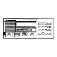
1.1 Display Unit........................................................................................................................1-1
1.2 Distributor Unit ...................................................................................................................1-5
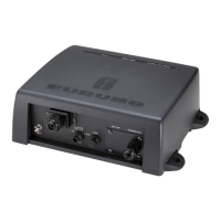
1.3 Transceiver Unit.................................................................................................................1-6
1.4 Transducer.........................................................................................................................1-8
1.5 Option Unit.......................................................................................................................1-22
2. WIRING....................................................................................................................2-1
2.1 Overview ............................................................................................................................2-1
2.2 Precautions for Cable Installation ......................................................................................2-2
2.3 Display Unit........................................................................................................................2-2
2.4 Distributor Unit ...................................................................................................................2-5
2.5 Transceiver Unit...............................................................................................................2-10
2.6 Junction Box (option) .......................................................................................................2-12
2.7 Grounding ........................................................................................................................2-14
3. ADJUSTMENTS ......................................................................................................3-1
3.1 [EQUIPMENT] sub menu...................................................................................................3-3
3.2 [I/O] sub menu ...................................................................................................................3-6
3.3 [SIMULATION] sub menu ..................................................................................................3-7
3.4 [MAINTENANCE] sub menu ..............................................................................................3-8
3.5 [TEST] menu....................................................................................................................3-12
3.6 [DS-8510 DATA]/[DS-8520 DATA] sub menu..................................................................3-20
3.7 [EQUIP RESET] sub menu ..............................................................................................3-20
3.8 How to Set SFI.................................................................................................................3-20
3.9 How to Offset for Analog Port ..........................................................................................3-21
APPENDIX 1 JIS CABLE GUIDE .............................................................................AP-1
APPENDIX 2 DIGITAL INTERFACE .......................................................................AP-2
APPENDIX 3 CALIBRATION....................................................................................AP-7
PACKING LISTS ......................................................................................................... A-1
OUTLINE DRAWINGS ................................................................................................ D-1
INTERCONNECTION DIAGRAM ................................................................................ S-1