1. MOUNTING
1-6
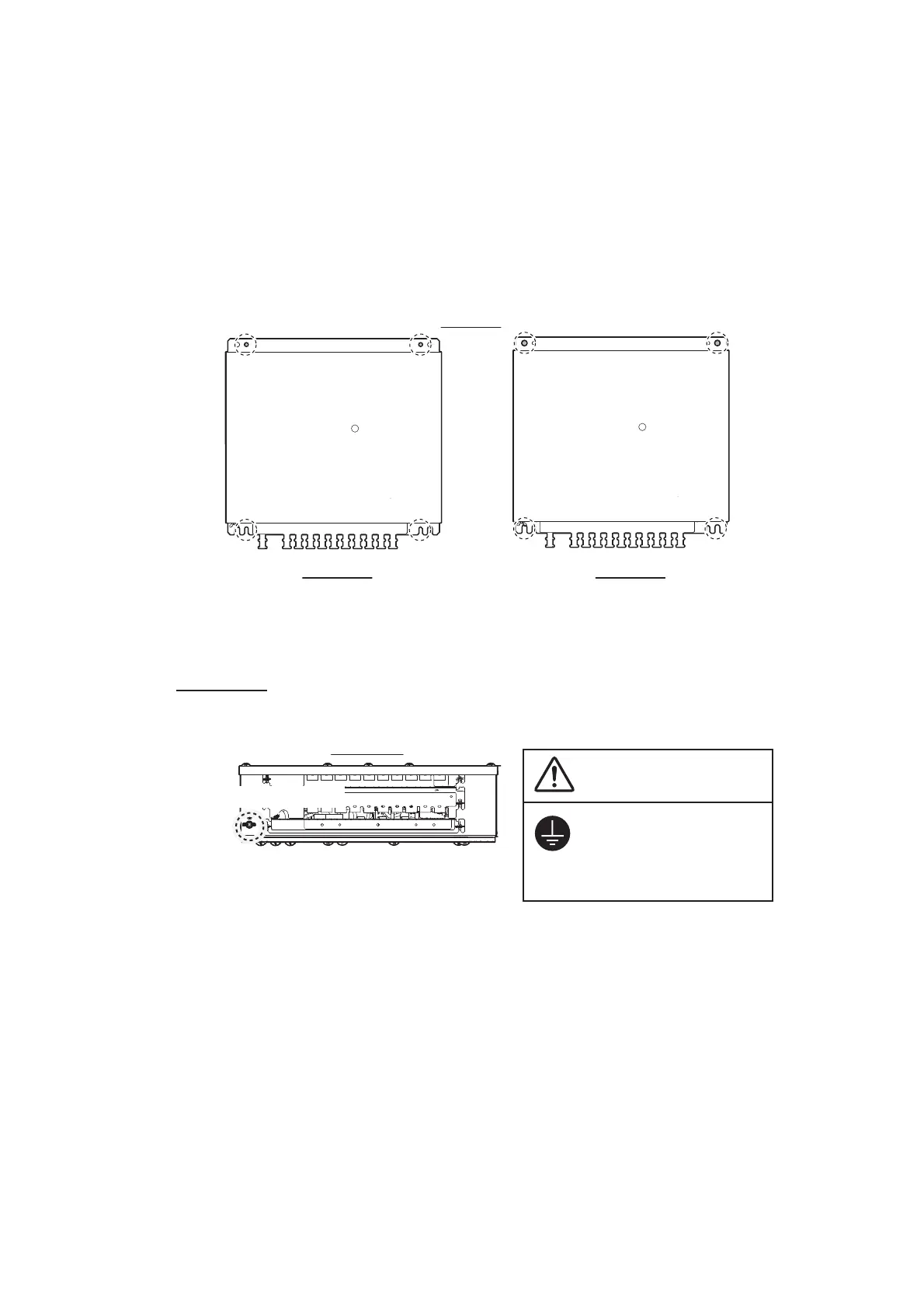
1.2.2 Mounting
Use M6 (supplied) or M8 (local supplied) screws. Note that the size of mounting holes
etc. differ according to the screw size.
Note:
For bulkhead installations, the cable entry must face downward.
1. Make four pilot holes, referring to the outline drawing at the back of this manual.
2. Fit two self-tapping screws at the location for the bottom fixing holes. Leave ap-
proximately 5 mm of thread exposed. The mounting holes and notches differ ac-
cording to the mounting screws.
3. Place the distributor unit on the two screws and fasten two self-tapping screws to
the top fixing holes.
4. Fasten the two self-tapping screws at the bottom fixing holes tightly.
Grounding
Ground the unit with the supplied ground wire referring to the figure to the right.
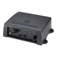
1.3 Transceiver Unit
This unit can be installed on a bulkhead.
1.3.1 Installation considerations
Keep in mind the following points when selecting a location.
• Locate the transceiver unit away from heat sources to prevent heat build up inside
the cabinet.
• Select a location where the vibration is minimal.
• Locate the equipment away from places subject to water splash and rain.
Top view
M6 screw M8 screw
Notch
(Inside)
Inside
Outside
Notch
(Outside)
Front view
Ground terminal
CAUTION
Ground the equipment
to prevent electrical
shock and mutual
interference.
 Loading...