EasyManua.ls Logo

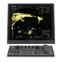
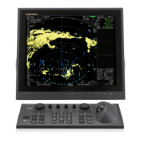
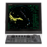
Furuno FAR-2218 User Manual

Furuno FAR-2218
332 pages
To Next Page IconTo Next Page
Page #1 background imageLoading...
Page #1 background image
FAR-2218
FAR-2218-BB
FAR-2228
FAR-2228-BB
FAR-2228-NXT
FAR-2228-NXT-BB
FAR-2238S
FAR-2238S-BB
FAR-2238S-NXT
FAR-2238S-NXT-BB
FAR-2318
FAR-2328
FAR-2328-NXT
FAR-2328W
FAR-2338SW
FAR-2338S
FAR-2338S-NXT
FAR-2018-MARK-2
FAR-2028-MARK-2
OPERATOR'S MANUAL
www.furuno.com
Model
MARINE RADAR

Table of Contents

Other manuals for Furuno FAR-2218

Questions and Answers:

Furuno FAR-2218 Specifications

General IconGeneral
TypeMarine Radar
Display TypeLCD
Screen Size10.4 inches
Power Output25 kW
Antenna TypeOpen Array
WeightApprox. 45 kg (Antenna Unit)
Power Supply24 VDC
Display Size10.4 inches
Range Scales0.25, 24, 48 nautical miles
Antenna Size6 feet
Operating Frequency9410 MHz ±30 MHz
FrequencyX-band
Antenna Length1.2 m
Beamwidth1.9° (Horizontal)
Rotation Speed24 RPM

Summary

IMPORTANT NOTICES

General

Important user guidance and disclaimers for manual usage.

How to discard this product

Instructions for environmentally responsible disposal of the product.

How to discard a used battery

Guidelines for the safe and proper disposal of batteries.

SAFETY INSTRUCTIONS

General Safety Warnings

Crucial warnings about electrical hazards, antenna rotation, and safe operation.

Radio Frequency Radiation Hazard

Information on potential risks from RF energy emitted by the radar antenna.

FOREWORD

Features

Overview of the radar's key capabilities and model configurations.

Terminology standards used in this manual

Definitions of terms and commands used throughout the manual.

SYSTEM CONFIGURATION

NOTICE

Important notes regarding sensor interconnection and system setup.

X-band (TR-UP, CF Antenna)

Details the system configuration for X-band TR-UP radars with CF antennas.

S-band (TR-UP)

Details the system configuration for S-band TR-UP radars.

1. OPERATIONAL OVERVIEW

1.1 Controls Overview

Introduction to the available control units (RCU-014, RCU-015/016).

1.5 Menu Operations

Guide to opening, closing, and navigating the radar's menus.

1.9 How to Set Up Function Keys

Procedure for assigning functions to the programmable keys (F1-F4).

1.12 How to Set Own Ship’s Speed

Instructions for inputting own ship speed for TT and stabilization.

1.15 User Settings

Information on saving, loading, and resetting user configurations.

1.19 How to Adjust Sensitivity

Instructions for adjusting the radar receiver gain (sensitivity).

1.34 Collision Assessment by Offset EBL

Function to assess collision risk using offset EBL measurements.

1.37 Target Trails

Displays historical target movement paths for better situational awareness.

1.39 Target Alarm

Sets alarm zones to alert navigators to targets entering specific areas.

1.49 Performance Monitor

Monitors radar transmitter power and receiver sensitivity for performance checks.

1.55 How to Manage SD Card Data

Procedures for managing data (marks, settings, tracks) on an SD card.

2. RADAR OBSERVATION

2.1 General

Explains fundamental radar concepts like minimum and maximum range.

2.1.4 Radar resolution

Details bearing and range resolution capabilities of the radar.

2.1.5 Bearing accuracy

Explains factors affecting the accuracy of target bearing measurements.

2.2 False Echoes

Identifies and explains common types of false radar echoes.

2.3 SART (Search and Rescue Transponder)

Information on how the radar detects and displays SART signals.

3. TARGET TRACKING (TT)

3.1 Precautions when Using Target Tracking

Essential warnings and considerations before using the TT system.

3.5 How to Acquire and Track Targets

Steps for acquiring and maintaining tracking on radar targets.

3.6 How to Enter Own Ship Speed

Methods for inputting own ship speed for accurate target tracking.

3.15 Collision Alarm (CPA, TCPA)

Features for calculating and alerting on potential collision risks.

3.16 Acquisition Zone

Defines areas for automatic target acquisition and alerting.

3.18 TT System Messages

Lists and explains various system messages and alerts for TT.

3.21 Factors Affecting Target Tracking

Discusses environmental and operational factors impacting target tracking accuracy.

4. AIS OPERATION

4.1 Controls for AIS

Identifies the control unit keys for operating AIS functions.

4.3 How to Select the AIS Display Mode

Procedures for choosing how AIS data is presented on the display.

4.5 How to Use the AIS Display Filter

Allows filtering out unnecessary AIS objects to declutter the display.

4.6 How to Activate AIS Targets

Methods for manually activating or automatically activating AIS targets.

4.7 How to Sleep AIS Targets

Procedures for changing AIS targets from active to sleeping status.

4.12 AIS Lost Alert

Alerts for when AIS objects are lost or fail to transmit data.

4.14 AIS Collision Alarm (CPA, TCPA)

Calculates and alarms for CPA/TCPA thresholds for AIS targets.

4.15 How to Associate TT and AIS Targets

Links TT and AIS targets to present a single symbol for the same vessel.

4.17 How to Use AIS Messages

Functions for creating, saving, transmitting, and viewing AIS messages.

5. VIDEO PLOTTER OPERATION

5.2 How to select a mark type

Guides on selecting different types of marks for the radar map.

5.4 Radar Map

Functionality for creating and displaying radar maps with symbols and lines.

5.5 Origin Mark

Allows marking prominent targets or points of interest with origin marks.

5.8 Own Ship and Other Ship’s Track

Displays historical tracks for own ship and tracked targets.

5.9 How to Use Waypoints

Manages waypoints for navigation, including entry, editing, and display.

5.10 Routes

Allows display, editing, and management of navigation routes.

5.11 Chart Functions

Features related to displaying and aligning ECDIS charts on the radar.

6. MAINTENANCE, TROUBLESHOOTING

Safety Warnings

Critical safety information before performing any maintenance.

6.1 Periodic Maintenance Schedule

Recommended routine checks and maintenance tasks for the equipment.

6.5 Easy Troubleshooting

Common problems and their solutions for restoring normal operation.

6.6 Advanced-level Troubleshooting

Procedures for hardware and software issues requiring qualified personnel.

6.7 Diagnostics

Instructions for executing the system's diagnostic test program.

6.9 Fallback Arrangements

How the system automatically switches to backup sensors during failures.

APPX. 1 MENU TREE

1 ECHO

Tree structure for the ECHO menu, detailing processing functions.

3 NAV TOOLS

Tree structure for Navigation Tools menu items.

4 ALERTS

Tree structure for the Alerts menu, detailing notification settings.

5 TT•AIS

Tree structure for Target Tracking and AIS functions.

2 BRILL

Tree structure for Brilliance and Color settings.

4 USER SETTINGS

Tree structure for managing user settings and presets.

6 FUNCTION KEY SETUP

Tree structure for assigning functions to the programmable keys.

APPX. 2 LONGITUDE ERROR TABLE (96 NM SCALE)

APPX. 3 ALERT LIST

ALF format alerts

Lists aggregated header alerts, their meanings, and priority.

APPX. 4 DATA COLOR AND MEANING

APPX. 5 ABBREVIATIONS

APPX. 6 SYMBOLS

General radar symbols

Visual guide to common symbols displayed on the radar screen.

TT symbols

Explains the symbols used for Target Tracking (TT) information.

AIS symbols

Explains the symbols used for Automatic Identification System (AIS) targets.

APPX. 7 PARTS LOCATION

Control Unit RCU-014

Diagram showing the internal components of the RCU-014 control unit.

Processor Unit RPU-025

Diagram illustrating the internal components of the RPU-025 processor unit.

RF Unit RTR-108 (FAR-2328W)

Illustrates the internal components of the RTR-108 RF unit.

SPECIFICATIONS OF MARINE RADAR FAR-2xx8 SERIES

1 ANTENNA RADIATOR

Technical details of the radar antenna, including beam width and sidelobe attenuation.

3 PROCESSOR UNIT

Technical specifications for the processor unit, including range and bearing performance.

3.10 Target tracking (TT)

Lists target tracking capabilities such as acquisition and vector settings.

3.11 AIS

Details AIS display capacity and tracking capabilities.

6 POWER SUPPLY

Information on the power requirements for different system components.

9 PERFORMANCE MONITOR

Technical details and parameters of the radar's performance monitor.

Related product manuals