3
3. MOUNTING THE EQUIPMENT
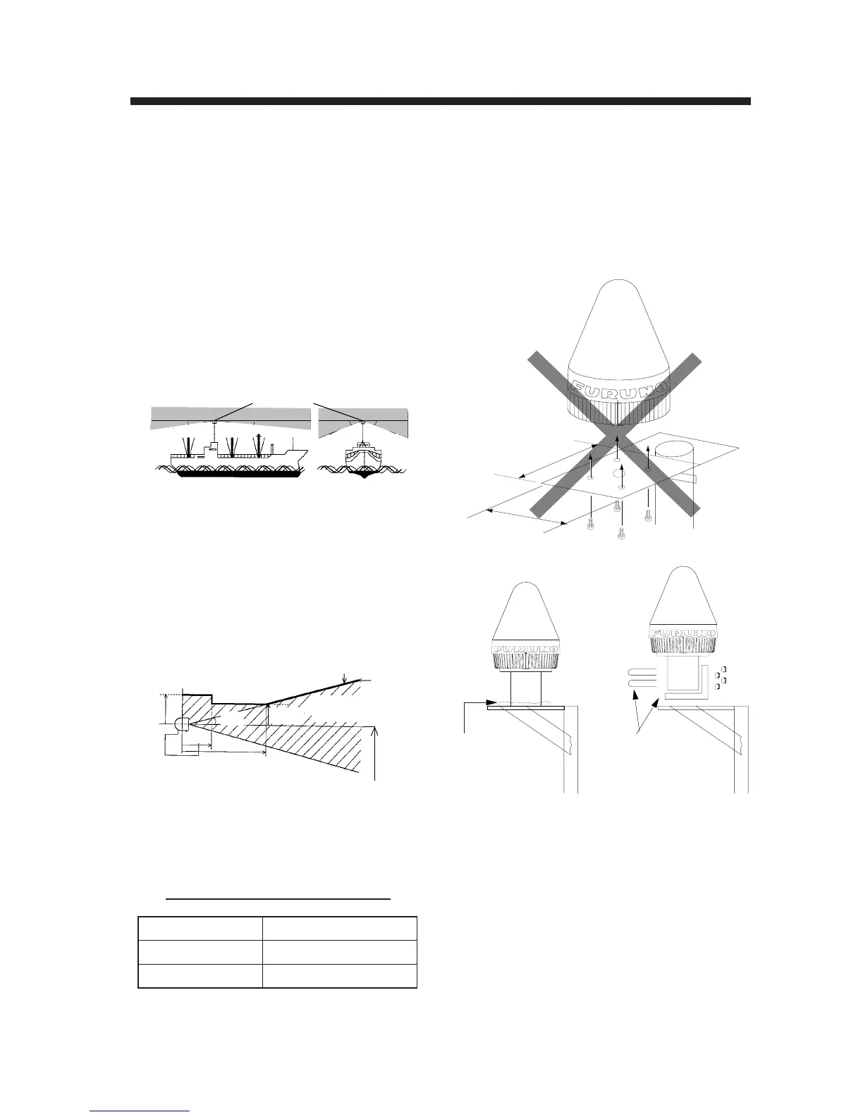
5) Avoid the location near funnels and stacks;
smoke and soot on the radome can lower sig-
nal level.
6) Never mount the antenna unit on a metal
plate more than 20 cm square. Use the an-
tennal mounting pipe (supplied), or fix or
weld it to a bracket as shown below.
more than
20 cm
more than
20 cm
elding
Use bracket
and hose clamp
(local supply)
Figure 3-3 Mounting the antenna
Mounting Location
Antenna unit
1) Mount the omnidirectional antenna high atop
a mast clear of stays and the turning diam-
eter of a radar scanner. The ideal mounting
location would be where no obstacle appears
in the fore and aft directions down to -5˚ and
down to -15˚ in the port and starboard direc-
tions. This concept is illustrated in
Figure 3-1. Shadow sector of the antenna
mast, whip antenna, etc. should be within 2
degrees at one meter from the antenna unit.
ANTENNA UNIT
5˚5˚
15˚ 15˚
Figure 3-1 Antenna unit mounting location
2) If both Inmarsat-A/B and Inmarsat-C ship
earth stations are installed, separate the
Inmarsat-A/B antenna at least 8 m from the
Inmarsat-C antenna.
3) Separate the antenna unit from an S-band
radar as follows:
2 m
2 m
5 m
S band radar
1.5 m
HORIZONTAL LINE
Install above this line
PROHIBITED
ZONE
INSTALLATION
ZONE
15˚
Figure 3-2 S band radar and installation area
4) The allowable vibration level as specified by
Inmarsat is as shown in the table below.
Table 3-1 Allowable vibration level
ycneuqerFleveL
zH01ot2edutilpmAkaePmm45.2
zH001ot01s/m8.9
2
noitareleccAkaeP
 Loading...