M
Melanie ClarkSep 9, 2025
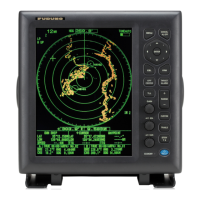
How to improve range discrimination on Furuno FR-8122?
- JJacob AlexanderSep 9, 2025
If you're experiencing poor discrimination in range with your Furuno Marine Radar, try adjusting the A/C SEA control.
How to improve range discrimination on Furuno FR-8122?
If you're experiencing poor discrimination in range with your Furuno Marine Radar, try adjusting the A/C SEA control.
Why are the range rings not showing on my Furuno Marine Radar?
If the range rings are not displayed on your Furuno Marine Radar, adjust their brilliance on the Brill/Color menu. If that's unsuccessful, the associated circuit board may need to be replaced. If problems persist, replace the SPU Board.
How to fix Furuno FR-8122 Marine Radar if power cannot be turned on?
If your Furuno Marine Radar power won't turn on, the fuse may be blown, so replace it. Check the wiring and input voltage to ensure they are correct. If the problem persists, the power supply board may need replacement.
How to troubleshoot Furuno Marine Radar if you cannot turn on the power?
If your Furuno Marine Radar doesn't turn on, check the fuse to see if it's blown. Ensure the power connector is firmly fastened and inspect the power cable connector for corrosion. Also, check the power cable for damage and verify the battery's voltage output is within the range of 10.8-31.2 V.
Why is my Furuno Marine Radar sensitivity poor even when tuned properly?
If your Furuno Marine Radar is properly tuned but sensitivity is poor, turn off the 2nd-trace echo rejector from the Echo menu. Clean any dirt from the radiator face. If the issue persists, with the radar transmitting on 48 nm range, check the magnetron current; if it's below normal, replace the magnetron. Also, check the MIC detecting current; if it's below normal, the MIC may have become detuned.
What to do if Furuno Marine Radar key is not responding?
Turn off and on the power. If there still is no response the key may be faulty. Contact your dealer for advice.
Why is the interference rejector not working on my Furuno Marine Radar?
If the interference rejector is not working, and the interference rejection level is not displayed on your Furuno Marine Radar, the SPU Board may need to be replaced.
Why is echo stretch not working on my Furuno FR-8122 Marine Radar?
If the echo stretch is not working, and neither ES1, ES2, nor ES3 is displayed on your Furuno Marine Radar, the SPU Board may need to be replaced.
How to fix Furuno FR-8122 Marine Radar when target not tracked correctly?
If targets are not being tracked correctly on your Furuno Marine Radar, and there's poor definition of targets in sea clutter, adjust the A/C SEA and A/C RAIN controls.
Furuno Marine Radar: marks appear, but no noise or echo. What to check?
If, when adjusting the GAIN with A/C SEA set to minimum on your Furuno Marine Radar, marks and indications appear but there's no noise or echo, check the continuity and isolation of the coaxial cable. If the cable is not the issue, the IF amplifier may need to be replaced. If the problem persists, check the coax line for a secure connection. If the connection is good, replace the SPU board.
Details RF radiation hazards from the radar antenna and safe distances.
Warnings about electrical shock hazards and proper fuse usage.
Information on warning labels attached to equipment and TFT LCD properties.
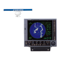
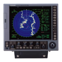
Lists key features and specifications of the FR-8xx2 radar models.
Details specification types (River, Sea, IEC) and function availability.
Describes the keys, knobs, and trackball on the main display unit.
Explains the functions of the optional remote controller for armchair operation.
Step-by-step guide for powering the radar on, off, and initiating transmission.
Explains the various elements and indicators shown on the radar screen.
Instructions for adjusting the brightness and dimmer settings of the display.
Explains how to navigate and operate the radar's menu system.
Guide for performing automatic or manual tuning of the radar receiver.
Details the different radar display modes available for navigation.
Instructions on how to switch between the available presentation modes.
Explains the characteristics of each presentation mode (Head-up, Course-up, etc.).
Guide for selecting and adjusting the radar's display range scale.
Instructions for selecting pulse length for optimal target detection and resolution.
Selecting between automatic and manual gain adjustment methods.
How to set the automatic gain level based on sea conditions.
Procedure for manually adjusting gain for optimal visibility of noise and echoes.
Selecting between automatic and manual sea clutter suppression.
How to set the automatic suppression level for sea clutter based on conditions.
Procedure for manually adjusting sea clutter suppression for better target visibility.
Selecting between automatic and manual rain clutter suppression.
How to set the automatic suppression level for rain clutter.
Procedure for manually adjusting rain clutter suppression for better target visibility.
Step-by-step guide to using the Variable Range Marker (VRM) for range measurement.
How to select the unit of measurement for the VRM (nm, km, sm, kyd).
Step-by-step guide to using an EBL to measure target bearing.
Explains how to reference EBL bearings as relative or true.
Step-by-step guide for defining a target alarm zone on the radar screen.
How to silence the audio component of a target alarm.
Selecting whether alarms trigger for targets entering or exiting a zone.
Procedure to temporarily disable active target alarms without erasing zones.
How to fully remove target alarm zones and their indicators from the screen.
Setting the echo strength level that will trigger a target alarm.
How the display automatically shifts based on ship's speed.
How to manually shift the display origin to a desired cursor position.
Step-by-step instructions for activating and using the zoom feature.
Selecting the type of zoom mode for target tracking or display.
Instructions for activating and deactivating the target trails display.
Selecting between true or relative motion for displaying target trails.
Choosing between single or multiple gradation for target trails.
Selecting the color used for displaying target trails.
Setting the target strength level for generating trails.
How trail copy maintains trails when changing range scales.
Enabling thinner trails for better visibility with many targets.
Option to display a trail for the user's own ship.
How trails restart when the range scale is changed.
Selecting preset trail lengths or custom time intervals.
How to enable or disable the parallel index lines feature.
How to set the orientation and interval for parallel index lines.
Selecting between parallel or vertical orientation for index lines.
Setting TLL mode for outputting position, inscribing marks, or both.
Choosing whether origin marks move relative to ship or are fixed.
Explains the purpose of custom setups and default options.
Details the available settings and their configurations within custom setups.
Step-by-step guide to configuring and naming custom radar setups.
Using predefined color schemes for daytime, nighttime, and twilight.
How to select custom echo and background colors.
How navigation data is shown on the screen when the radar is in standby.
How to configure the display to show navigation data at the bottom.
Steps to navigate to and open the radar's initial menu.
Explains the various customizable items within the initial sub menu.
Steps to turn on and display GPS buoy information on the radar screen.
Selecting the color for GPS buoy symbols on the display.
Configuring the display of past positions (history dots) for GPS buoys.
How to remove GPS buoy symbols and their tracks from the radar screen.
Explains the factors defining minimum and maximum detecting ranges of the radar.
Defines bearing and range resolution and factors affecting them.
Factors influencing the accuracy of radar bearing measurements.
Explains measuring range using fixed rings and Variable Range Marker (VRM).
Describes multiple echoes and methods for reducing them.
Describes sidelobe echoes and methods for reducing them.
Explains virtual image false echoes caused by mirror effects.
Describes shadow sectors caused by obstructions blocking the radar beam.
Explains how a SART appears on the radar display and its characteristics.
Details on SART range errors, radar bandwidth, and side lobes.
Crucial precautions and cautions for using the ARP auto plotter effectively.
Explains the controls used for ARP operations including ENTER, CANCEL, MENU, and Trackball.
How to enable or disable the ARP target display on the radar screen.
How to acquire and track up to ten targets manually or automatically.
Step-by-step instructions for manually acquiring targets with the ARP.
Setting up an automatic acquisition area for targets within a specific range and bearing.
Procedures for cancelling tracking of individual or all ARP targets.
How to stop tracking a specific selected target.
How to cancel tracking for all acquired ARP targets simultaneously.
Setting vector time duration and reference (True or Relative).
Explains controls for interacting with AIS targets and menus.
How to enable or disable the AIS target display on the radar screen.
Explains the different symbols used to represent AIS targets.
How to convert sleeping targets to activated and vice-versa.
How to show detailed data for AIS targets in the data box.
Setting the display range for viewing AIS targets.
Sorting AIS targets by range, sector, CPA, or TCPA.
Filtering AIS targets to display only those within a defined sector.
Choosing the quantity of AIS targets to be shown on the screen.
Customizing AIS target vectors for speed, course, and reference.
Displaying past positions of tracked AIS targets.
Setting and managing CPA/TCPA alarms for AIS targets for collision avoidance.
Setting proximity alarms for AIS targets entering a specified range.
How the system indicates when AIS data is no longer received from a target.
Procedure to clear all lost AIS targets from the radar display.
Choosing the color for AIS target symbols on the display.
Selecting the type of GPS navigator connected to the radar.
Choosing the datum type that matches nautical charts for accurate positioning.
Setting up WAAS for more accurate position data using geostationary satellites.
Displaying information about GPS and WAAS satellites for signal status.
Receiving and displaying weather information from Japanese DGPS reference stations.
Adjusting for differences in GPS sensor and radar antenna installation positions.
Performing a cold start to clear GPS almanac data when needed.
Important warnings regarding equipment handling, electrical shock, and RF hazards.
Regular maintenance tasks for the LCD, terminals, and antenna unit.
Instructions for replacing fuses and warnings about using correct types.
Information on magnetron lifespan and LCD backlight life expectancy.
How to clean the trackball for smooth cursor movement.
Basic troubleshooting steps for common operational issues.
Troubleshooting procedures for hardware/software issues, typically for qualified technicians.
How to run diagnostic tests to check system operation.
Performing an LCD pattern test to check color display functionality.
Running a GPS self-test to verify the connected GPS receiver's operation.
Overview of settings for brightness, color, and display schemes.
Settings related to echo adjustment, stretch, and averaging.
Settings for trail mode, gradation, color, level, and length.
Customizable functions assignable to F1 and F2 keys.
Covers range, pulse length, PRR, max range, resolution, accuracy.
Table showing antenna rotation speed and pulse length selection by range.
Details frequency, modulation, output power, and IF.
Describes the LCD display size, resolution, and effective area.
Lists various alphanumeric indications shown on the radar display.
Specifies the audio alarm volume level.
Details the rated voltage and current for the radar's power supply.
Specifies operating ambient temperature, humidity, and waterproofing.
Specifies the coating colors for the display unit and antenna unit.
| Brand | Furuno |
|---|---|
| Model | FR-8122 |
| Category | Marine Radar |
| Language | English |