Do you have a question about the Furuno FR-2155 and is the answer not in the manual?
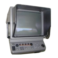
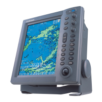
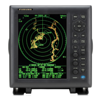
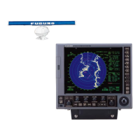
Provides an overview of the FR-2155 radar and its major configuration components.
Lists the various boards and major components for the Display Unit, Power Supply Units, and Scanner Unit.
Details the technical specifications for the Scanner Unit, Transceiver, Display Unit, environmental conditions, and power.
Presents a high-level overview, system configuration, and simplified block diagram of the FR-2155 radar.
Illustrates the Display Unit's internal block diagram and details the functions of its major boards.
Details the SPU board's block diagram, functions, and signal processing features like echo averaging.
Provides ARPA block diagrams, target acquisition, tracking, and initial setting procedures.
Illustrates block diagrams for the AC Power Supply units and the Scanner Unit components.
Highlights hazardous voltage warnings and essential safety precautions before performing adjustments.
Details procedures for adjusting the Display Unit, including brightness, contrast, and display size.
Identifies the location of key components and boards within the Display Unit and associated power supplies.
Details adjustment procedures for the Scanner Unit, including RF unit and various board component locations.
Highlights hazardous voltage warnings and essential safety precautions before performing maintenance.
Explains the function of DIP switches and jumper settings for system configuration.
Describes LED status indicators and the self-test procedure for diagnosing system health.
Provides guidance on replacing major parts like the magnetron and updating system programs.
Lists and explains error messages and visual alarms indicating system abnormalities.
Provides flow charts to help diagnose and resolve system problems based on symptoms.
| Antenna Rotation Speed | 24 RPM |
|---|---|
| Display Type | LCD |
| Operating Temperature | -15°C to +55°C |
| Frequency | 9410 MHz (X-band) |
| Range Scales | 0.25, 0.5, 0.75, 1.5, 3, 6, 12, 24, 48 nm |
| Beam Width | 1.9° (horizontal) |
| Power Supply | 100-240 VAC |
| Antenna Length | 6 ft (1.8 m) |