Do you have a question about the Furuno FR-1510 and is the answer not in the manual?
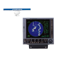
Describes the radar's features and general capabilities.
Lists the main circuit boards and their functions within the display and scanner units.
Details technical parameters for scanner and transceiver units.
Covers display parameters, I/O, NAV data, and environmental conditions.
General system architecture and signal flow.
Detailed schematic of the display unit's internal connections.
Explains the role of individual circuit boards in the display unit.
Step-by-step process of system initialization upon power-on.
Traces the path of video signals within the system.
Explains the automatic receiver tuning process.
Explanation and illustration of echo averaging feature.
Explanation of the clutter sweep function for noise reduction.
Overview diagram of the ARPA system architecture.
Details on ARPA target acquisition and tracking capabilities.
Details the DC power supply's components and functions.
Details the AC power supply's components and functions.
Details on general, radiator, gear box, and RF unit.
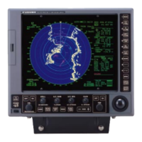
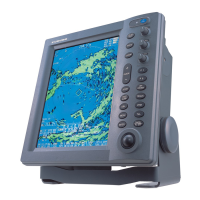
Location of major parts and controls on the display.
Procedures for adjusting display screen settings.
Details on adjusting the scanner unit components.
Adjustment procedures for specific RF modules.
Configuration settings via DIP switches and jumpers.
Interpretation of LED indicators for board status.
Steps and results for system self-testing.
Steps for updating the radar system software.
Guidance on replacing critical components like magnetron and boards.
Description and meaning of error messages and alarms.
Overview of diagnostic flow charts for troubleshooting.
Troubleshooting steps for display malfunctions.
Troubleshooting for missing heading, navigation, or antenna rotation data.
Diagnosing problems with sensitivity, echoes, and target acquisition.
Overall system wiring schematic.
Detailed diagrams for the display unit.
Diagrams for power supply units.
| Power Output | 10 kW |
|---|---|
| Range | 96 nm |
| Range Scales | 0.25 to 96 nm |
| Frequency | 9410 MHz (X-band) |
| Beam Width | 1.9° (Horizontal) |
| Rotation Speed | 24 rpm |