Do you have a question about the Furuno FR-2165DS and is the answer not in the manual?
Hazards from radar RF emissions and safe operating distances.
Warnings on electrical dangers and need for qualified personnel during installation and service.
Crucial safety notices regarding power supply compatibility, grounding, and general operational precautions.
Guidance on selecting location, orientation, and mounting considerations for the radar scanner unit.
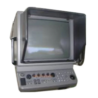
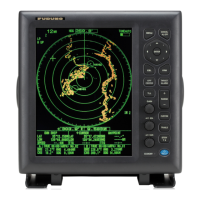
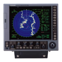
Procedures and considerations for mounting the display unit, including tabletop and console types.
Detailed steps for fabricating and connecting signal cables to the scanner unit.
Procedures for fabricating and leading power and signal cables to the display unit.
Steps for initializing and tuning the radar system for optimal performance.
How to access and navigate the radar's initialization and adjustment menus.
Procedure for adjusting the video amplifier input level to ensure clear target echoes.
Calibrating the radar's heading display relative to the ship's actual heading.
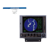
Diagram showing overall connections between scanner, power supply, and display units.
Detailed circuit diagram of the scanner unit's internal components and connections.
Circuit diagram for the PSU-004, showing power distribution and components.
Circuit diagram for the PSU-001, illustrating its internal wiring and components.
| Type | Marine Radar |
|---|---|
| Range | 0.125 to 96 nautical miles |
| Power Output | 25 kW |
| Rotation Speed | 24 RPM |
| Frequency | 9410 MHz ± 30 MHz |