Do you have a question about the Furuno FR-2135S and is the answer not in the manual?
Warns about potential eye harm from radar RF energy emitted by the scanner.
Details risks associated with electrical work and working at heights on the scanner.
Covers power supply compatibility, proper grounding, and avoiding water exposure.
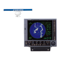
Lists all parts included in the standard Furuno FR-2135S radar package.
Lists optional accessories and add-on modules for the radar system.
Provides guidelines for locating and installing the scanner unit.
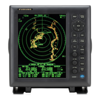
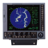
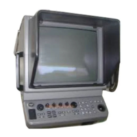
Instructions for mounting the display unit in tabletop or console configurations.
Details installation of the PSU-004, including location and compass safety.
Covers fabricating and routing the power cable for the display unit.
Explains the process for preparing multicore and signal cables for the scanner.
Steps for initial radar tuning and navigating setup menus.
How to adjust video signal levels for clear target echoes.
Procedure to calibrate the radar's heading reference.
Adjusting sweep timing based on cable length for accurate display.
Method to eliminate or reduce the central artifact on the radar display.
Steps to check if the magnetron heater voltage is within specification.
Guides through setting up radar parameters like ship info and system modes.
Installing the GC-8 board to interface with a gyrocompass.
Installing the ARP board for ARPA functionality and subsequent adjustment.
Installing the RP board to enable video plotter functions.
Steps for installing the PM-50 performance monitoring unit.
Connecting the alarm kit to the ship's bridge alarm system.
| Range Scales | 0.125 to 96 nautical miles |
|---|---|
| Rotation Speed | 24 RPM |
| Frequency | 9.4 GHz (X-band) |
| Display Size | 10.4 inches |
| Beamwidth | 1.2° |
| Antenna Type | Slotted waveguide array |