13
Place the stereo in the cutout.
14
Secure the stereo to the mounting surface using the included
screws
Á
.
15
Snap the screw covers in place
Â
.
Replacing an Existing Stereo
1
Remove and disconnect the existing stereo.
2
If necessary, remove the existing wiring harness or install a
vehicle- or vessel-specific wiring-harness adapter (not
included) to provide access to the power and speaker wiring.
3
Place the mounting gasket on the back of the stereo
À
.
4
Place the mounting bracket
Á
behind the mounting surface.
5
Make the necessary wiring connections (Connection
Considerations, page 2).
6
Place the stereo in the opening.
7
Secure the stereo to the mounting bracket using the included
screws
Â
.
NOTE: You might need to reach behind the mounting surface
to hold the bracket in place when securing the stereo to the
bracket.
8
Snap the screw covers in place
Ã
.
Connection Considerations
The stereo must be connected to power, to speakers, and to
media input sources to function correctly. You should carefully
plan the layout of the stereo, wired remote, speakers, optional
NMEA 2000
®
network, and your input sources before making
any connections.
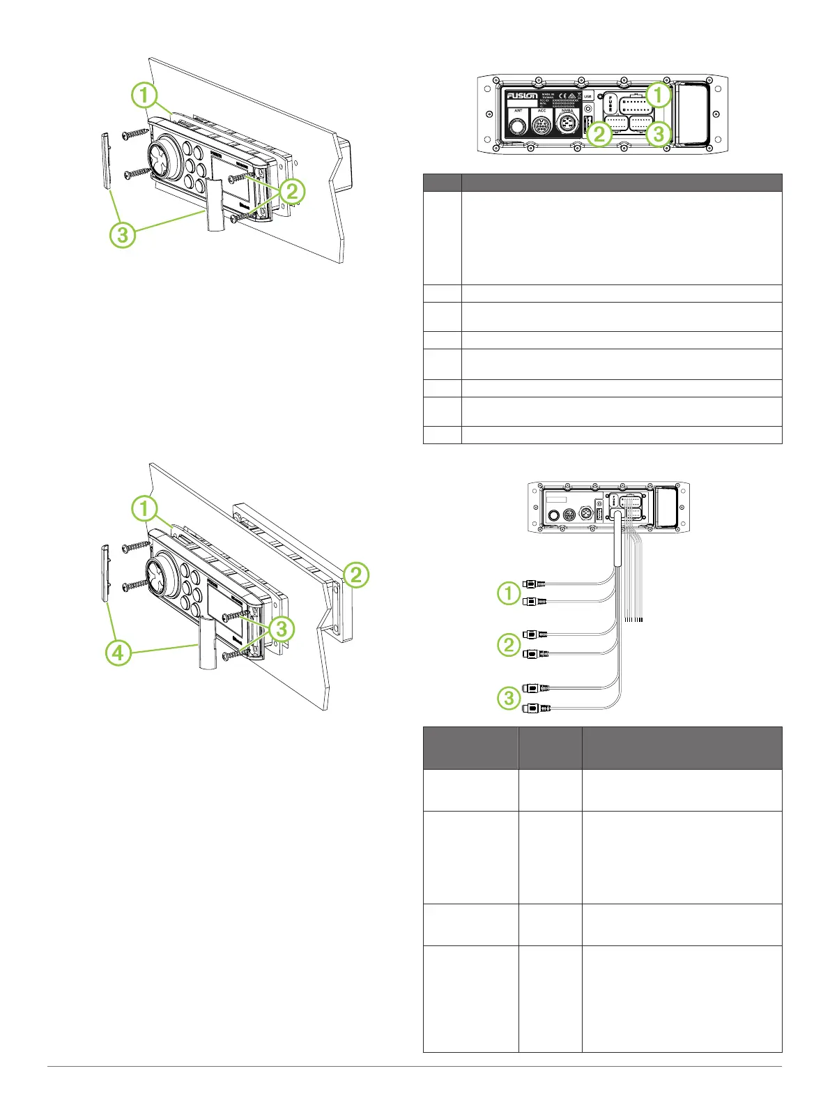
Port Identification
Item Description
ANT Connects the stereo to a typical AM/FM antenna using an RF
coaxial connector.
If you are installing the stereo on a boat with a metal hull, you
must use a ground-dependent antenna, and if you are installing
the stereo on a boat with a non-metal hull, you must use a
ground-independent antenna. See the installation instructions
provided with your antenna for more information.
ACC Reserved for future use.
NMEA Connects the stereo to a NMEA 2000 network ("N" models
only) (NMEA 2000 System Wiring Diagram, page 3).
USB Connects the stereo to a USB source.
FUSE Contains the fuse for the device.
See the device specifications for replacement fuse information.
À
Connects the stereo to the power and speaker wiring harness.
Á
Connects the stereo to the auxiliary in and line/subwoofer out
wiring harness.
Â
Reserved for future use.
Wiring Harness Wire and Connector Identification
Wire Function Wire
Color/
Number
Notes
Power (+) Yellow Connects to the positive terminal of a
12 Vdc power source capable of
supplying 15 A.
Ground (-) Black Connects to the negative terminal of a
12 Vdc power source capable of
supplying 15 A. This wire should be
connected before connecting the
yellow wire. All accessories connected
to the stereo must share a common
ground location.
Amplifier on Blue Connects to an optional external
amplifier to turn it on when the stereo
turns on.
Mute Brown Activates when connected to ground.
For example, when connected to a
compatible hands-free mobile phone,
the audio mutes or the input switches
to AUX when a call is received and the
phone connects this wire to ground.
This functionality can be configured
from the settings menu.
2 Fusion MS-RA70/MS-RA70N Installation Instructions

 Loading...