EasyManuals Logo

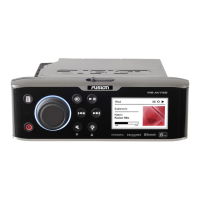
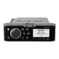
Fusion MS-UD/AV750 Quick Start Manual

Fusion MS-UD/AV750
17 pages
To Next Page IconTo Next Page
To Previous Page IconTo Previous Page
Page #10 background imageLoading...
Page #10 background image
Fusion™
MS·UD/AV650/750
Installation
Instructions
Failure
to
follow
these
warnings
and
cautions
could
result
in
personal
injury,
damage
to
the
vessel,
or
poor
product
performance.
~
--
·
-
·
~---
·-
---
--·--
See
the
Important
Safety
and
Product
Information
guide
in
the
product
box
for
product
warnings
and
other
important
information.
This
device
must
be
installed
according
to
these
instructions.
·
---
----·-••••-<0•-••-•••·-----
---
-----
----M-•
"* ''*'* ''
''-"
*•*'"-
'"'
* '_ " _ ._,,,
___
____
,
__
__
_ __ __
,,_,_
,_
,_,,_,
___
,
____
_____
__
,_
Disconnect
the
vessel's
power
supply
before
beginning
to
install
this
product.
--
--
·-··
·-
---
··
·
··
..
·
··
"""
'''' ''
"""""
'
''
"'
""
'
""'
- ''
''''
* '
•''•--
- -
---
----
--
--
----
...
..
. ..
..
....
..
.
..
....
..
......
........... .
..
.. ..
,_
.
_____
_
_______
~-
-
-··
...
........ '
..
..
..
...
..
.
__________________
___
___
___
________
_
Before
applying
power
to
this
product,
make
sure
it
has
been
correctly
grounded,
following
the
instructions
in
the
guide
.
Always
wear
safety
goggles,
ear
protection,
and
a
dust
mask
when
drilling,
cutting,
or
sanding.
NOTICE
When
drill
i
ng
or
cutting,
always
check
what
is
on
the
opposite
side
of
the
surface.
You
must
read
all
installation
instructions
before
beginning
the
installation
.
If
you
experience
difficulty
during
the
installation,
contact
Fusion
Product
Support.
Two
Mounting
plates
Mounting
hardware
o
Four
8-gauge
,
self-tapping
screws
o
Four
M4
machine
screws
Power
and
speaker
wiring
harnesses
RCA
splitter
Micro-USB
to
USB
cable
(UD
models
only}
Lightning™
connector
to
USB
cable
(UD
models
only}
Apple
®
30-pin
to
USB
cable
(UD
models
only}
Remote
control
(AV
models
only}
Two
AM
batteries
(AV
models
only}
Phillips
screwdriver
Electric
drill
Drill
bit
(size
varies
based
on
surface
material
and
screws
used}
Rotary
cutting
tool
or
jigsaw
Marine
sealant
(optional}
The
stereo
must
be
mounted
in
a
location
where
there
is
enough
clearance
for
the
open
door
of
the
ster
eo as
indicated
on
the
template
.
The
stereo
must
be
mounted
in
a
location
that
allows
open
airflow
around
the
rear
of
the
stereo
for
heat
ventilation.
The
stereo
must
be
mounted
within
45
°
of
the
horizontal
plane.
The
cable
should
have
a
drip
loop
to
allow
water
to
drip
down
off
the
cable
and
avoid
damaging
the
stereo
.
If
you
want
to
mount
the
stereo
outside
the
boat,
it
must
be
mounted
in
a
location
well
above
the
waterline
,
where
it
is
not
submerged.
If
you
wan
t
to
mount
the
stereo
outside
the
boat,
it
should
be
mounted
in
a
location
where
it
will
not
be
damaged
by
a
docks,
pilings,
or
other
pieces
of
equipment.
To
avoid
interference
with
a
magnetic
compass,
the
stereo
should
be
installed
at
least
15
em
(5.9
in.}
away
from
a
compass.
Mounting
the
Stereo
NOTICE
Be
careful
when
cutting
the
hole
to
flush
mount
stereo
.
There
is
only
a
small
amount
of
clearance
between
the
case
and
the
mounting
holes
,
and
cutting
the
hole
too
large
could
compromise
the
stability
of
the
stereo
after
it
is
mounted.
Before
mounting
the
stereo,
you
must
choose
a
location
following
the
guidelines
above
.
1
Trim
the
template
and
make
sure
it
fits
in
the
selected
location.
2
Secure
the
template
to
the
selected
location.
3
Using
a
drill
bit
appropriate
for
the
mounting
surface,
drill
the
hole
inside
the
corner
of
the
dashed
line
on
the
template
to
prepare
the
mounting
surface
for
cutting.
4
Using
a ji
gsaw
or
rotary
tool,
cut
the
mounting
surface
along
the
inside
of
the
dashed
line
indicated
on
the
template.
5
If
necessary,
remove
the
sun
cover
from
the
stereo.
6
Place
the
stereo
in
the
cutout
to
test
the
fit.
7
If
necessary,
use
a
file
and
sandpaper
to
refine
the
size
of
the
cutout.
8
After
the
stereo
fits
correctly
in
the
cutout
,
ensure
the
mounting
holes
on
the
stereo
line
up
with
the
pilot
holes
on
the
template
.
9
If
the
mounting
holes
on
the
stereo
do
not
line
up
,
mark
t
he
new
pilot-hole
locations.
10
Using
an
appropriately
sized
drill
bit
for
the
mounting
surface
and
screw
type
,
drill
the
pilot
holes.
11
Remove
the
template
from
the
mounting
surface.
12
Connect
the
wiring
harnesses
and
wires,
while
observing
polarity.
13
Place
the
mounting
gasket
on
the
back
of
the
stereo
0)
.

Other manuals for Fusion MS-UD/AV750

Questions and Answers:

Question and Answer IconNeed help?

Do you have a question about the Fusion MS-UD/AV750 and is the answer not in the manual?

Fusion MS-UD/AV750 Specifications

General IconGeneral
BrandFusion
ModelMS-UD/AV750
CategoryMarine Audio
LanguageEnglish

Related product manuals