Magnus Hedlund Page 3
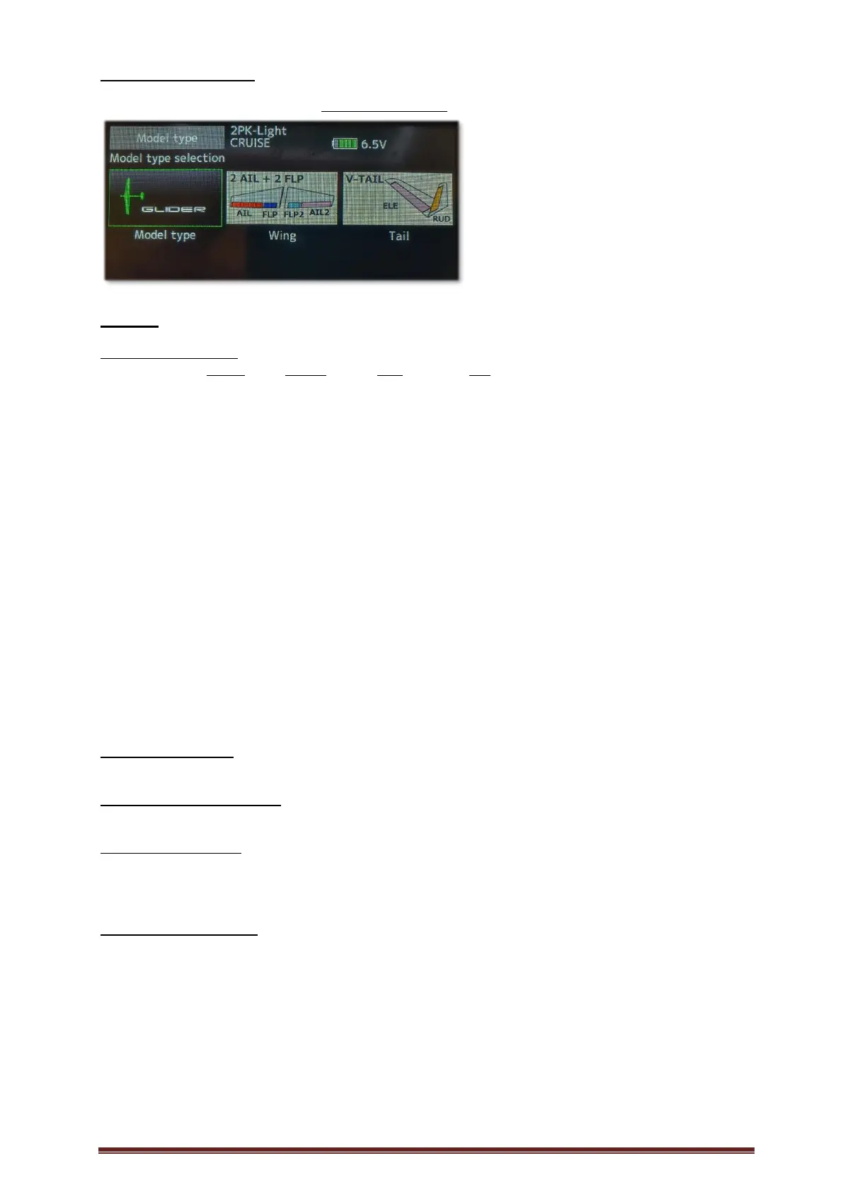
First, select the model type:
LINKAGE – MODEL TYPE
When, if later on, changing model type all settings will be lost.
BASIC: SETUP ‘GLIDER’
LINKAGE – FUNCTION (Channel output, control, trim)
Output Control Trim Info
1: ELEVATOR J2 T2 Elevator (alt. V-Tail)
2: RUDDER J4 T4 Rudder (alt. V-Tail)
3: AILERON J1 T1 Aileron Left
4: AILERON2 - - - - Aileron Right
5: FLAP - - - - Flap Left
6: FLAP2 - - - - Flap Right
7: MOTOR SB - - Motor
8: AUX1 - - - -
9: AUX2 - - - -
10: AUX3 - - - -
11: AUX4 - - - -
12: AUX5 - - - -
13: AUX6 - - - -
14: AUX7 - - - -
15: BUTTERLY J3 - - Brake
16: CAMBER LS - -
DG1: - -
DG2: - -
The above is an example of where to set the channel outputs. (SB is chosen as Motor control.)
Set the channel outputs before setting up the model.
LINKAGE – SUB TRIM
All = 0 Change neutral position for the servo.
LINKAGE – SERVO REVERSE
All = Normal (MOTOR = Reverse)
LINKAGE – END POINT
ELE, RUD, AIL, AIL2: 152, 100, 100, 152
FLAP, FLP2: 152, 140, 140, 152 (for max brake possibility)
MOT: 152, 114, 100, 152 (for max = 2000 us)
GLIDER – COND. SELECT (Flight Conditions)
CONDIT1, Rename to CRUISE (Lowest priority)
ADD CONDIT2, Rename to THERMAL
ADD CONDIT3, Rename to THERMAL2
ADD CONDIT4, Rename to DISTANCE
ADD CONDIT5, Rename to LANDING
ADD CONDIT6, Rename to MOTOR ON (Highest priority)
MOTOR ON Switch = “SA” On = down
LANDING Switch = “J3”, Normal, Linear, Hysteresis, Off = -92, On = -90
DISTANCE Switch = “SC” On = up
THERMAL2 Switch = Logic: “SC” and “SH”, SC On = down, “SH” On = down
THERMAL Switch = “SC”, On = down