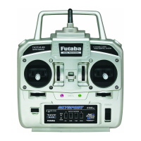
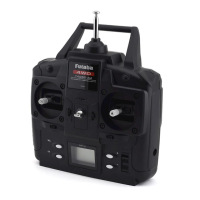
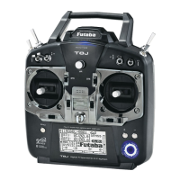
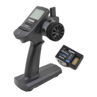
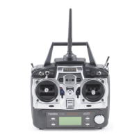
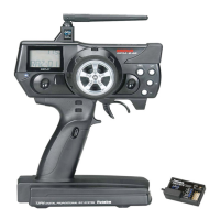
The device is a Futaba 4YF-2.4GHz FHSS (Futaba Frequency Hopping Spread Spectrum) digital proportional R/C airplane system. It is designed for beginner flyers and includes a T4YF-2.4G transmitter and an R2004GF receiver.
Function Description:
The Futaba 4YF-2.4GHz system provides 4-channel radio control for model airplanes. The transmitter operates on the 2.4GHz band using FHSS technology, which helps avoid interference from other systems through a unique ID code. The system allows for precise control of ailerons, elevator, throttle, and rudder. It includes servo reversing on all channels and a factory-set, pre-programmed "wing-type" mixer for elevon mixing, which can be activated for tailless models like delta wings and flying wings. The elevon mixing allows channel 1 (aileron) and channel 2 (elevator) to operate in unison (as elevators) or in opposition (as ailerons), requiring each elevon to be operated by a separate servo. The transmitter features adjustable-length control sticks for user comfort and trim levers for fine-tuning the neutral position of servos and engine idle RPM. A "Power Down Mode" is included for performing ground range checks, reducing RF power for a limited time. The system also supports a trainer function, allowing a student to practice flying with an instructor using a separate Futaba transmitter and a trainer cord.
Important Technical Specifications:
Transmitter (T4YF-2.4G):
- System: FHSS 2.4GHz, 2-stick, 4-channel.
- Operating Band: 2.4GHz.
- Power Supply: 6V (4 AA size batteries).
- Current Drain: 90mA.
- Antenna: Built-in (internal).
Receiver (R2004GF):
- System: FHSS 4-channel receiver.
- Operating Band: 2.4GHz.
- Power Requirement: 4.8V or 6V (shared with servo).
- Current Drain: 30mA (at no signal).
- Dimensions: 1.54 x 1.02 x 0.39 inches (39 x 26 x 10 mm).
- Weight: 0.49 oz. (14g).
- Compatibility: Designed to work specifically with the T4YF-2.4G transmitter. Not compatible with current Futaba FASST systems.
- Battery Warning: Never use dry batteries for the receiver power supply as they may cause difficulties.
Usage Features:
- Servo Reversing: Allows users to change the direction of servo response to control inputs. It is crucial to check all controls after reversing to ensure correct operation.
- Trim Settings: Four trim levers are provided for aileron, elevator, rudder, and throttle to adjust the neutral position of servos and engine idle RPM. Trims should be centered initially, and pushrods adjusted so control surfaces are centered.
- Centering Servos: A procedure is outlined to center servos by connecting them to the receiver, turning on the transmitter and receiver, centering control sticks and trims, and then attaching servo arms perpendicularly to pushrods.
- Elevon Mixing: A specialized function for tailless models (flying wings, delta wings) that mixes aileron and elevator channels for combined control of elevons. Activated by a switch inside the battery compartment.
- Trainer Function (Student only): Enables a student to control the model while connected to an instructor's Futaba transmitter via a trainer cord. The instructor can take over control by releasing a switch.
- Adjustable-Length Control Sticks: The length of the control sticks can be adjusted for user comfort by turning the stick tip and locking piece.
- Power Down Mode: A special mode for ground range checks, reducing RF power for 90 seconds. Activated by holding the Power Down switch during transmitter power-on. The red LED blinks fast in this mode.
- Link Procedure: The receiver must be linked with the transmitter's unique ID code for operation. This involves placing the transmitter and receiver close, turning both on, and holding the Link switch on the receiver until the LED turns solid green. A double-check of servo response after linking is recommended.
Maintenance Features:
- Regular Maintenance: It is recommended to send the transmitter to a Futaba Service Center annually for checkups and service, especially during the non-flying season.
- Battery Management:
- Transmitter: Uses 4 AA batteries. Users are warned to insert batteries with correct polarity and remove them during long periods of non-use to prevent leakage and corrosion. A slow blinking red LED indicates a low battery alarm (approx. 4.2V), prompting immediate landing.
- Receiver Ni-Cd Batteries: Requires careful charging. Batteries are supplied partially charged and need a full overnight charge before first use. Charging can be done directly to the battery pack or through the on/off switch. The charger's LED indicates charging status. Fast charging requires following manufacturer instructions and never exceeding 1,000mA. Periodic discharge (cycling) is recommended every one to two months to prevent "memory effect" and maintain battery capacity. Batteries should be replaced if capacity drops noticeably.
- Radio Installation Guidelines:
- Connectors: Ensure alignment tabs on battery, switch, and servo connectors are correctly oriented when plugging into the receiver. Pull on plastic connectors, not wires, when unplugging.
- Servo Mounting: Servos must be mounted with supplied rubber grommets to prevent vibration transmission and premature wear. No part of the servo casing should contact the airframe structure.
- Servo Arm Alignment: Servos should be centered, and servo arms placed perpendicularly to pushrods. Pushrods should be adjusted for centered control surfaces.
- Control Surface Movement: After installation, operate servos through full travel to check for binding or contact between pushrods and servo arms. Address any buzzing sounds from servos, indicating resistance.
- Receiver Switch: Mount the receiver on/off switch on the side of the fuselage, away from engine exhaust, ensuring full, unrestricted motion.
- Receiver Antenna: The antenna must be kept at least half an inch away from conductive materials (metal, carbon). The coaxial part should not be bent sharply. Keep the antenna away from the motor, ESC, and other potential RF noise sources.
- Receiver Protection: The receiver contains delicate electronic parts and should be protected from vibration, shock, and temperature extremes using Velcro or other vibration-absorbing material. Waterproofing with a plastic bag is recommended to protect against moisture, fuel, and exhaust residue.
- Pre-Flight Checks:
- Control Check: Before every flight, operate all controls to ensure correct response and check for inadvertent movement or abnormal servo sounds.
- Range Check: A ground range check using "Power Down Mode" is mandatory before the first flight of a new model and recommended before the first flight of each day. This involves walking away from the model while operating controls to confirm adequate operational range (approx. 10m/33ft). A second range check with the engine running at various speeds is advised to check for servo jitter or inadvertent movement.
- Power On/Off Sequence: Always turn on the transmitter first, then the receiver. When turning off the system, always turn off the receiver first, then the transmitter. This prevents damage to servos or unexpected motor activation.