Do you have a question about the FUTABA 4PL-2.4GHZ and is the answer not in the manual?
Key symbols used in the manual and their meanings.
Essential checks to perform before operating the R/C system.
Correct procedure for turning the transmitter and receiver power on/off.
Critical warnings regarding charging and handling of NiMH/NiCd batteries.
Warnings concerning children, heat, fire, and battery disassembly.
Summary of the product's main features, including communication and memory.
Feature for setting Futaba ESC parameters via transmitter.
Servo compatibility and response mode selection for HIGH mode.
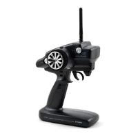
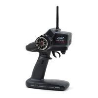
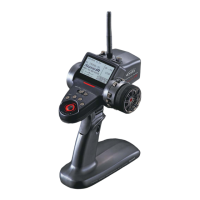
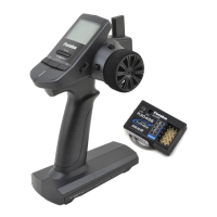
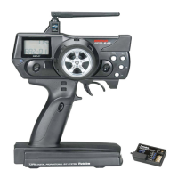
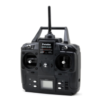
Labeled diagram illustrating the parts of the T4PL transmitter.
Step-by-step guide for replacing the transmitter's AA batteries.
Alert for low transmitter battery voltage, requiring immediate action.
Procedure for replacing the transmitter battery with an optional rechargeable one.
Method for charging the optional rechargeable battery.
Warnings related to charger operation, including wet hands and voltage.
Explanation of PWR ON mode (transmitting) and DISP mode (checking data).
How the power-off forgotten alarm operates and can be deactivated.
Steps to adjust the mechanical ATL for brake stroke.
Steps to adjust the spring tension of the wheel and trigger.
Steps to adjust the throttle trigger's forward/backward position.
Warnings about handling the antenna to prevent damage.
Steps to link the transmitter and receiver using unique ID codes.
Important considerations and potential issues during the linking process.
Critical warnings regarding potential receiver mislinking.
Safety guidelines for installing and routing the receiver antenna wire.
Setting the transmitter mode (HIGH/NORM) for receiver compatibility.
Diagrams showing how to connect the receiver and servos to the ESC or battery.
Safe routing and placement of antenna wire away from noise sources.
Methods for protecting the receiver from vibration and moisture.
Ensuring all connectors are securely connected to prevent loss of control.
Proper mounting of servos using rubber grommets to prevent vibration.
Adjusting servo range and linkage to prevent binding or strain.
Warning about potential short circuits from ESC heat sink contact.
Importance of installing capacitors to suppress motor noise.
Initial steps before setting up transmitter functions.
Verifying the receiver type (FHSS/S-FHSS) setting.
Selecting response mode based on servo type (HIGH/NORM).
Initial setup and verification of the steering trim.
Initial setup and verification of the throttle trim.
Sequence of initial setup steps for installing servos in a car.
Setting servo direction and adjusting subtrim for neutral point.
Adjusting throttle trigger travel and end points (EPA).
Setting initial dual rate (DT3) and ATL (DT4).
How to navigate and operate the transmitter screens.
Method for calling and accessing various menu screens.
Model memory call, copy, reset, and receiver type selection.
Adjusting the maximum travel limit for servos.
Configuring fail safe and battery fail safe functions.
Creating custom channel mixing for advanced control.
Anti-skid braking system for improved cornering.
Adjusting front and rear brakes independently.
Mixing function for 4-wheel steering vehicles.
Mixing for vehicles using dual Electronic Speed Controllers.
Various throttle operation settings like neutral position and idle-up.
Connecting to ESC via software for parameter changes.
Methods to access and display the MODEL RX menu screen.
Procedure to select, copy, and reset model data.
Procedure to copy model data from one memory to another.
Procedure to reset selected model data to its factory defaults.
Configuration options for fail safe operation.
Function to activate fail safe on low battery voltage.
How to set up the fail safe function's servo position.
Steps to set up programmable mixing functions.
Setting the rate at which the servo returns after brake release.
Setting the delay for ABS activation.
Setting the point at which ABS begins to operate.
Setting the proportion of brake application and release time.
Overall steps to adjust the ABS function parameters.
Detailed steps for adjusting the cycle speed of ABS.
Detailed steps for setting the ABS trigger point.
Detailed steps for setting the ABS duty ratio.
Selecting the type of 4-wheel steering (e.g., reverse phase).
Procedure for adjusting dual ESC mixing.
Setting forward/brake ratios (5:5 or 7:3).
Function to raise idling speed for engine starting.
Procedure to set the idle-up rate.
Procedure to set the neutral brake rate.
Procedure to set the engine cut (throttle off) position.
How to use the ESC link feature to change ESC parameters.
Explanation of the UP timer's functionality.
How to start, stop, and use the UP timer.
Explanation of the FUEL DOWN timer for checking refueling time.
Explanation of the LAP timer's lap memorization.
How to operate the lap timer, including lap counting and stopping.
How to access and use the lap memory data.
Reference to the adjuster for steering and throttle correction.
Introduction to steering correction for mechanical offsets.
Calibrating the steering wheel's neutral position.
Calibrating the steering servo's maximum travel limits.
Introduction to throttle correction for mechanical offsets.
Calibrating the throttle trigger's neutral position.
Calibrating the throttle servo's maximum travel limits.
| Frequency | 2.4GHz |
|---|---|
| Channels | 4 |
| Modulation | FHSS |
| Telemetry | Yes |
| Display | LCD |
| Battery Type | 4x AA |
| Weight | 400g (with battery) |
| Model Memory | 40 |