10
Fasten about 5-10cm
from the servo outlet
so that the lead wire
is neat.
Margin in the lead wire.
To prevent the servo lead wires from being broken by vibration
during flight, provide a bit of slack so that the wire is not
pulling against the servo or connector going to the receiver. In
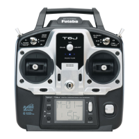
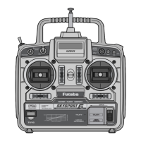
IMPORTANT: In order to maximize the performance and enjoyment of the Futaba T6J transmitter, please
read this section carefully and completely.
Receiver Installation:
In order to obtain the best possible performance from your 2.4GHz aircraft receiver, we have developed the
following guidelines and suggestions.
Antenna
*Must be kept as straight as possible.
Coaxial cable
The R2006GS has two antennas. In order to
maximize signal reception and promote safe
modeling Futaba has adopted a diversity antenna
system. This allows the receiver to obtain RF
To obtain the best results from the diversity function, please refer to the following instructions:
The two antennas must be kept as straight as possible. Failure to
do so might result in reduced operational range of the model.
Ideally, the two antennas should be placed at 90 degrees to each
other. However, the most critical aspect is to keep the antennas
away from each other as much as possible.
Larger models can have large metal objects that can attenuate the
RF signal. In this case the antennas should be placed at both sides of the model. Then the best RF signal
The antennas should be kept away from conductive materials, such as metal and carbon by at least half-
inch. The coaxial part of the antennas does not need to follow these guidelines, but do not bend in a small
radius.
Antenna Antenna