Do you have a question about the FUTABA 8FG SUPER and is the answer not in the manual?
Essential safety precautions for operating the R/C system.
Instructions for charging and managing Ni-MH/Ni-Cd batteries for safe operation.
Critical safety and handling instructions for Ni-MH/Ni-Cd batteries.
Guidelines for safely handling and storing Secure Digital memory cards.
Details on using SD cards for model data storage and software updates.
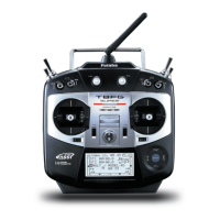
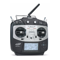
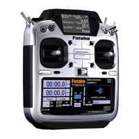
List of included components and technical data for transmitter and receiver.
Description of receiver ports (DATA, S.BUS) and system compatibility.
Detailed steps for charging the Ni-MH battery using the special charger.
Steps for turning the transmitter on and off, including RF condition check.
Information on low battery warnings and automatic transmitter power-off.
Step-by-step guide for linking the transmitter and receiver.
How to access and activate the transmitter's range check mode.
Detailed steps for performing a ground range check of the R/C system.
Instructions for connecting servos to the receiver and the S.BUS system.
Explanation and diagram for connecting devices using the S.BUS system.
Channel assignments for Airplane and Glider models based on wing type.
Selecting the correct model type (airplane, glider) and wing/tail types.
Adding and selecting helicopter models from memory.
Selecting helicopter model type and matching swash plate type.
Adding, deleting, copying, and renaming flight conditions.
Connecting servos according to kit manual and Linkage Menu functions.
Adjusting throttle and pitch curves for optimal helicopter performance.
Adjusting gyro sensitivity and operation mode for helicopters.
Mixing pitch inputs to rudder to correct torque effects.
How to start and set up the trainer system for instruction.
Selecting modes (NORM, MIX, FUNC) and switches for trainer operation.
Choosing the desired operation mode for each channel in trainer setup.
Setting the low battery alarm voltage threshold.
Accessing and setting up the Quick Select function for models.
Setting up Auto Lock via timer or start lock.
Adjusting the lock timer and enabling the start lock feature.
Performing moving and neutral servo tests.
Selecting models from transmitter memory or SD card.
Adding new model memories to the transmitter.
Selecting aircraft type (airplane, helicopter, glider) and related settings.
Selecting between FASST Multi-ch (MLT2/MULT) or 7ch modes.
Setting the transmitter's area mode for regulatory compliance.
Assigning functions (aileron, elevator) to servo output channels.
Fine-tuning servo neutral positions after linkage setup.
Changing the direction of individual servo responses.
Setting servo positions for lost signals or low battery voltage.
Setting and releasing battery fail safe functions.
Adjusting servo throws and differential throws.
Setting the limit point where servo throw stops.
Steps to activate and set the throttle cut function.
Procedure for lowering engine idling speed using a switch.
Limiting swash plate travel to a fixed range for helicopters.
Setting the neutral point for swash plate compensation.
Adjusting servo travel amounts for Aileron, Elevator, and Pitch.
Setting subtrim for servos during swash setup.
Adjusting pitch output using fixed or cyclic modes.
Options to reset digital trims or all model settings.
Assigning, deleting, or changing switches for flight conditions.
Copying conditions and customizing their operational priority.
Adjusting stick throw and curves for flight conditions or rates.
Accessing and setting up programmable mixes.
Adjusting pitch settings for VPP airplanes.
Optimizing engine speed based on throttle stick movement.
Slowing throttle stick response for turbine engine simulation.
Adjusting left/right aileron differential rates independently.
Adjusting up/down travel for each flap servo.
Mixing camber flaps with ailerons for improved roll characteristics.
Mixing brake flaps with ailerons for improved roll characteristics.
Mixing rudders with ailerons for steep banking.
Mixing ailerons with rudder input for roll maneuvers.
Adjusting camber and correcting elevators.
Mixing camber flaps with elevator to increase lift.
Correcting attitude changes when camber flaps are utilized.
Slowing aircraft and reducing altitude using ailerons and flaps.
Adjusting trim offset rates for ailerons, elevators, and flaps.
Using airbrakes for landing or diving maneuvers.
Dedicated mix for GYA Series gyros.
Adjustments for V-tail airplanes' rudder and elevator.
Improving roll axis performance by operating elevators as ailerons.
Adjusting rudder angles for airplanes with winglets.
Setting motor speed for EP gliders when started via switch.
List of core helicopter functions: PIT CURVE, THR CURVE, etc.
Details on hovering, high, and low pitch trim.
| Channels | 8 |
|---|---|
| Frequency | 2.4 GHz |
| Model Memory | 30 models |
| Telemetry | Yes |
| Modulation/System | FASST |
| Range | 1.5 km |
| Battery Type | NiMH |
| Display | LCD (128x64 dots) |