3
Physical Description
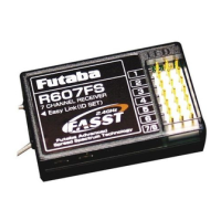
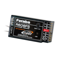
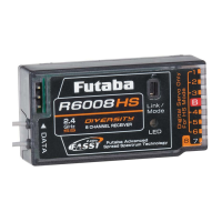
TM14-2.4G (Transmitter)
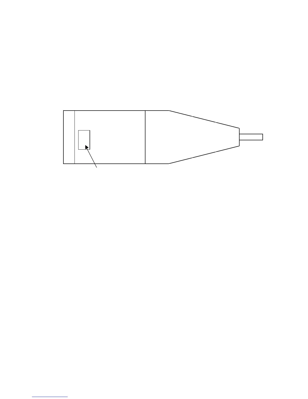
PIN ASSIGNMENT
BacksideoftheTM14
Ant.
10-pinconnectorforI/Ftotransmitter
Fig.1 TM14 communication port location
1.PlugtheTM14-2.4GintoyourT12FGtransmitter.
2.TurntheT12FGonandpleasechecktheLEDontheTM14becomesolidgreen
whenitʼsnormallyoperated.
3.Neverpointtheanntenatothemodelwhenflying.