Hz band offers different characteristics tha
the conventional 50MHz and 72MHz. As such, we strongl
ncourage you to read this manual care
ully prior to utilizing the TM-
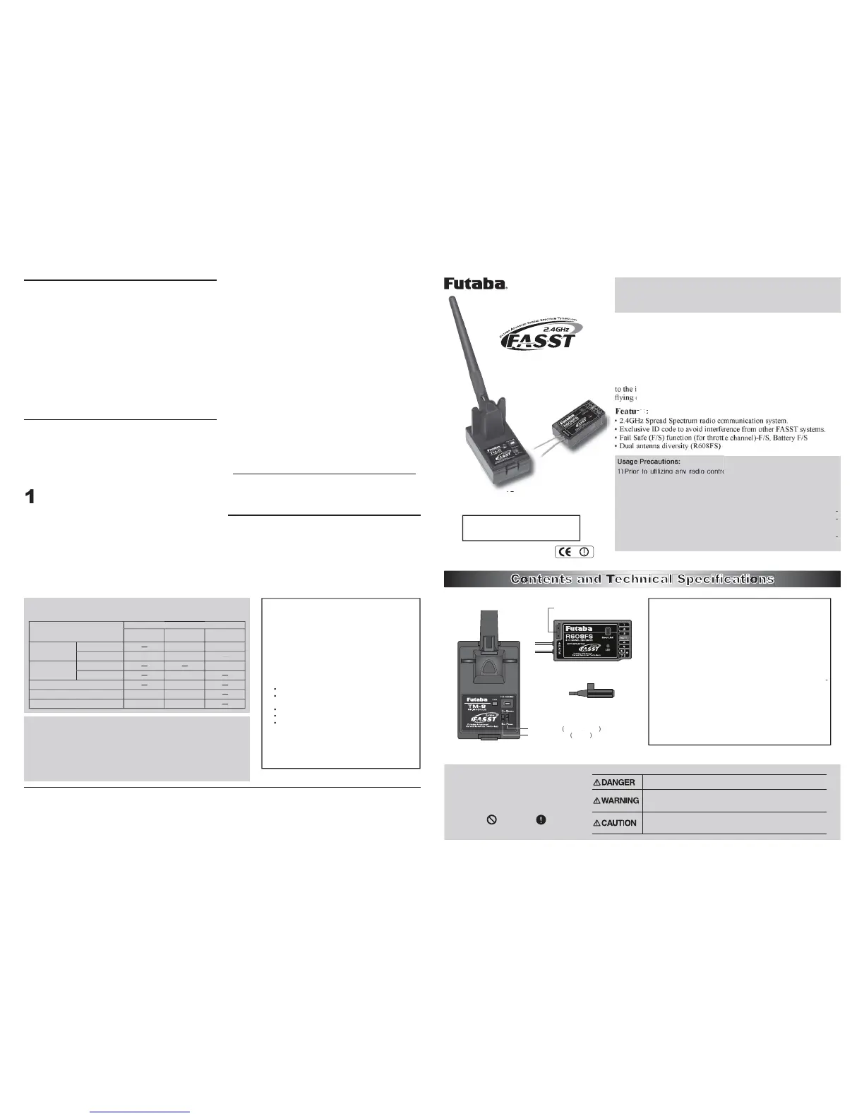
Your 2.4GHz system includes the following components
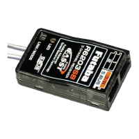
e TM-8 2.4GHz FASST transm
e
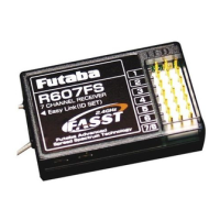
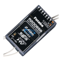
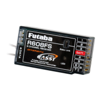
and R608FS receiver. This s
transmitter module and re
lace it with the TM-8 transmitter module. The
receiver R608FS, as the model number indicates, is capable of controllin
VWHPV
T7U, T8U, T9C and T9Z
epair Service (in U.S.A.)
IDQ\ GLI¿FXOWLHV DUHHQFRXQWHUHGZKLOH VHWWLQJXSRU RSHUDWLQJ
your TM-8 transmitter module and R608FS receiver, please
consu
ww.futaba-rc.com, www.2.4gigahertz.co
f you are unable to resolve the issue, pack the system in its
original container with a note enclosed and a thorough, accurate
HVFULSWLRQRIWKHGLI¿FXOW\,QFOXGHWKHIROORZLQJLQ\RXUQRWH
when the problem occurred)
stem (transmitter, Receiver,
odel numbers and quantity
our Name, Address and Tele
ective items to the authorized Futaba Service
002 N Apollo Drive Suite 1
Champai
Special Markings;
Pay special attention to the safety at
the parts of this manual that are
indicated by the following marks.
[Symbol] ; Prohibited ; Mandatory
Mark Meaning
Procedures which may lead to a dangerous condition and cause
death or serious injury to the user if not carried out properly.
Procedures which may lead to a dangerous condition or cause death
or serious injury to the user if not carried out properly, or procedures
where the probability of superficial injury or physical damage is high.
Procedures where the possibility of serious injury to the user is
small, but there is a danger of injury, or physical damage, if not
carried out properly.
unction
The TM-8 transmitter module and R608F
F/S
(failsafe). When the airborne volta
e
throttle stick to the predetermined position, after which
ou'll
have about 30 seconds of throttle control before the batter
from your time flying. The TM-8 transmitter module
incorporates a s
stem that reduces its power output and allows
link has been established
as indicated by either a solid
reen LED), press and hold the "F/S, Ran
e"
switch located on the rear of the TM-
transmitter module.
As indicated by the blinkin
red LED, the radio frequency
power has been reduced to allow
rom the model while simultaneously
operatin
the controls. Have an assistant stand
the model to confirm that all controls are completel
operational. You should be able to walk
pproximately 30-50 paces from the model without losin
operates correctly, return to the model.
et the transmitter in a safe, yet accessible, location
o it will be within reach a
ter starting the engine or motor.
hen start the engine or motor. Per
heck with your assistant holdin
at various speeds. If the servos jitter or
est you do not fly until the source of the
has been determined. Look for loose servo
Please make sure that you do not push and hold the F/S,
as this reduces the power
utput of the transmitter and reduces the overall ran
the trainer function of the transmitter as an
lease do not switch to the student's control
nit until the RF is active after turnin
Prior to utilizing any radio control system, it is strongly recommended
that you read and abide by the
ode created by the Academy of
odel Aeronautics as well as any site speci
reatly increase your enjoyment o
n order to maintain complete control of your aircraft it is important that
rasp the transmitter module's antenna durin
©Copyright 2008. No part of this manual may be reproduced in any form without prior permission. The contents of this manual are subject to change without prior
otice. While this manual has been carefully written, there may be inadvertent errors or omissions. Please contact our service center if you feel that any corrections or
FODUL¿FDWLRQVVKRXOGEHPDGH
FUTABA CORPORATION P
©FUTABA CORPORATION 2008, 01
To assure continued FCC com
$Q\FKDQJHVRUPRGL¿FDWLRQVQRWH[SUHVVO\DSSURYHGE\WKHJUDQWHHRIWKLVGHYLFHFRXO
void the user's authority to operate the equipment.
FCC La
ASST transmitter module, system and receiver
 Loading...