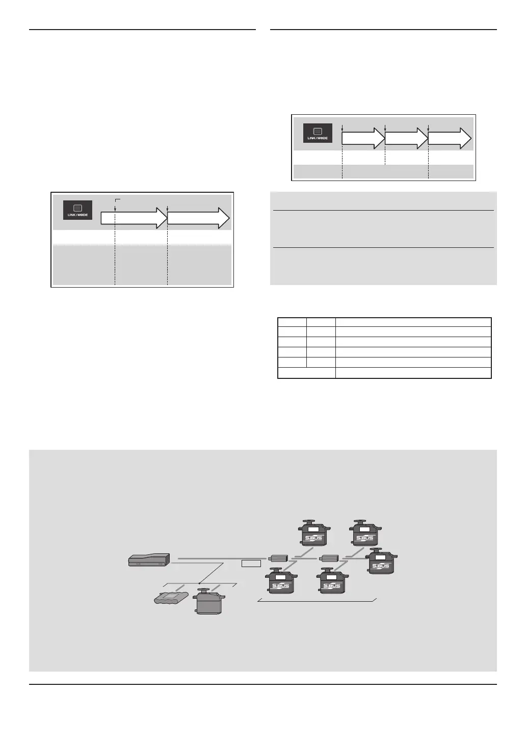
What is S.BUS?
Different from conventional radio control systems the S.BUS
system uses data communication to transmit control signals
from a receiver to a servo, gyro, or other S.BUS compatible
device. This data includes commands such as “move the
channel 3 servo to 15 degrees, move the channel 5 servo to
30 degrees” to multiple devices. The S.BUS devices execute
only those commands for their own set channel. For this
reason, it can be used by connecting multiple servos to the
same signal line.
[Connection by S.BUS system]
S.BUS hub S.BUS hub
S.BUS output
S.BUS
Ch output/
Battery terminal
R6203SB
Battery
S.BUS servo
Conventional
servo
2ch 4ch
3ch 5ch
6ch
* Set the channel at the S.BUSservosbyusinganSBC-1 channel changer or a CIU-2USBserialinterface.
*
Can also be used together with conventional servos. However, conventional servos cannot be used by the S.BUS output.
*
When using servos with a remote battery pack, use S.BUS Hub with Cable (2-way/remote battery pack use).
Please refer to the instruction manual of S.BUS Hub with Cable (2-way/remote battery pack use) for the connection method.
Operation Mode Select
The operation mode is on "Normal mode" from factory
shipping. When to change the mode, please follow the steps
shown below.
1
Turnoffthereceiver.
2
PressandholdtheLink/Modeswitch andturnon
thereceiver.Keeptheswitchholdmorethanone(1)
second. The LED startsflashing with thecurrent
status.
3
Release the switch.
4
Turnoffthereceiver.
By doing this step, the mode can switch over between two(2)
modes.
0 to 1 sec. More than 1 sec.
0 sec. 1 sec.
Press and Hold
Turn on the receiver.
No function
Showing the CURRENT
mode with blink.
Red Blink = Normal
Green/Red Blink =
High Speed
Solid as the mode changed.
Red Solid = Normal
Green/Red Solid = High
Speed
(Become Red after one (1)
second)
(Function)
To change the mode between
Normal and High Speed
(LED
Status)
Please check the operation mode by observing the LED when
turning on the receiver. If possible there's no FASST transmitter
turned on around you in order to make rmer check.
When turn on the receiver, the LED will be;
•Redwhenon"Normalmode"
•Green and Red (makesOrange) when on "High Speed mode".
(Aftertwo(2)seconds,changetoRed.)
If there are some FASST transmitter turned on around the
receiver, the LED may show the above status for a brief
moment then changed to the status indication as shown in the
"LED indication" table.
WARNING
Donotperformthelinkingprocedurewith
motor's main wire is connected or the engine is
operatingasitmayresultinseriousinjury.
Whilethelinkingisdone,pleasecyclereceiver
powerandcheckifthereceivertobelinkedis
reallyunderthecontrolbythetransmittertobelinked.
FUTABA CORPORATION
1080 Yabutsuka, Chosei-mura, Chosei-gun, Chiba-ken, 299-4395, Japan
Phone: +81 475 32 6982, Facsimile: +81 475 32 6983
1M23N17437 ©FUTABA CORPORATION 2011, 1 (1)
LED Indication
Green Red Status
Solid Solid Initializingwhenon"HighSpeedmode"
Off Solid No signal reception
Solid Off Receiving signals
Blink Off ReceivingsignalsbutIDisunmatched
Alternate blink Unrecoverableerror(EEPROM,etc.)
Link to the transmitter
1
PressandholdtheLink/Mode switch more than
two(2)seconds.
Re-adjust the F/S position (only for TM-8)
1
PressandholdtheLink/Modeswitchbetweenone(1)
andtwo(2)seconds.
0 to 1 sec. 1 to 2 sec. More than 2 sec.
0 sec. 1 sec. 2 sec.
Press and Hold
No function
With TM-8
(not included in this set)
To set the F/S
position(No re-link)
Re-link(ID set) and to
set the F/S position
No function
Other than TM-8
(not included in this set)
Re-link(ID set)
 Loading...